BryanMcPhail.com

Professional software development, amateur BMW tinkering, old arcade game stuff

By

EPOS The Glob / Beastie Feastie / Eeekk! hardware encryption

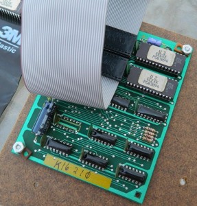
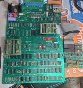
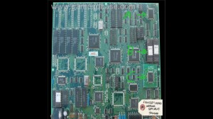
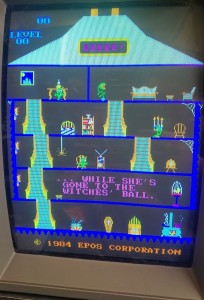
The EPOS games Glob, Super Glob, Beastie Feastie and Eeekk! run on Pacman hardware with a custom daughterboard. They use an obfuscated security system to prevent swapping the games just by burning the ROMs. Although these games are all emulated in MAME the security PAL chip for Beastie Feastie was not dumped until recently which meant the games couldn’t be repaired on real hardware until then (Although MAME had dumps for the PALs, they are all confirmed bad and did not work on real boards). The Eeekk! board is very rare and can not be found to be dumped, so I was asked if it’s possible to recreate the Eeeek! PAL based on the Beastie Feastie PAL and MAME information. And after some thought, yes…! Let’s see how.. this will get pretty technical though…

Screenshot_20230106-180043_Gallery

20230106_181439

    Part 1

First let’s look at the equations that come from the Beastie Feastie .JED file. ‘o’ means output (o19 = pin 19 on the PAL used for output). ‘i’ means input (i4 = pin 4 on the PAL used for input). / means invert/negate. * means AND. + means OR. Rather confusingly pin 11 is a double negative – it’s negated in the input section /i11=11 and negated everywhere it’s used in the equations.

i1=1 i2=2 i3=3 i4=4 i5=5 i6=6 i7=7 i8=8 i9=9 GND=10 /i11=11 o12=12
o13=13 o14=14 o15=15 o16=16 o17=17 o18=18 o19=19 VCC=20

o19 = /i4 * /i7 * /i9 * /i11
+ /i5 * i7 * /i9 * /i11
o18 = /i1 * /i8 * /i9 * /i11
+ /i6 * i8 * /i9 * /i11
o17 = i6 * /i8 * /i9 * /i11
+ /i3 * i8 * /i9 * /i11
o16 = /i2 * /i7 * /i9 * /i11
+ i4 * i7 * /i9 * /i11
o15 = /i3 * /i8 * /i9 * /i11
+ i1 * i8 * /i9 * /i11
o14 = i5 * /i7 * /i9 * /i11
+ /i2 * i7 * /i9 * /i11
/o13 = i9 * /i11
o12 = /i9 * /i11

And the physical connections to the encryption PAL on the board:

PAL10H8 inputs

1: D7 from encrypted program ROM
2: D6 from encrypted program ROM
3: D4 from encrypted program ROM
4: D3 from encrypted program ROM
5: D1 from encrypted program ROM
6: D0 from encrypted program ROM

7: LS193 Q0
8: LS193 Q1
9: LS193 Q2
11: LS193 Q3

The LS193 is a 4 bit counter, that can provide a 4 bit (16 states) encryption key to the PAL. The program code can modify the counter state, which means the encryption can change dynamically as the program executes! In theory this means the program could be impossible to statically decrypt and run in the same amount of ROM as it can ‘read itself’ and each byte would have 16 permutations the code could rely on (in practice we’ll see later only 4 permutations are used). This is an interesting aspect to the original security – as to statically decrypt the 4 (or 16) states would mean using 4 or 16 times as many ROMs which would have been cost prohibitive for a commericial pirate.

Most of the outputs go to a LS244 buffer chip that passes through to the Z80 CPU.

19: o19 -> LS244 1A1 -> 1Y1 -> D7 Z80
17: o17 -> LS244 1A2 -> 1Y2 -> D5 Z80
15: o15 -> LS244 1A3 -> 1Y3 -> D3 Z80
14: o14 -> LS244 2A2 -> 2Y2 -> D2 Z80
16: o16 -> LS244 2A3 -> 2Y3 -> D4 Z80
18: o18 -> LS244 2A4 -> 2Y4 -> D6 Z80
12: o12 -> LS10 pin 1 (3 input NAND)
13: o13 -> LS10 pin 2 (3 input NAND)

So 6 of the 8 bits are decrypted by the PAL, and 2 of the bits go directly via a LS04 invertor. Outputs 12 & 13 seem to be involved in program ROM enable*, they are not involved in encryption and must be the same between all games for the enable circuit to work, so we don’t need to worry about them. (*Update from HudsonArcade – these drive the LS244 enables, the ROM select is just regular A13 from the CPU. Thanks!).

Let’s look at things from the LS244 point of view

PAL o19 -> 1A1 -> 1Y1 -> D7 Z80
PAL o17 -> 1A2 -> 1Y2 -> D5 Z80
PAL o15 -> 1A3 -> 1Y3 -> D3 Z80
(LS04 12) -> 1Y4 -> D1 Z80
(LS04 10) -> 2Y1 -> D0 Z80
PAL o14 -> 2A2 -> 2Y2 -> D2 Z80
PAL o16 -> 2A3 -> 2Y3 -> D4 Z80
PAL o18 -> 2A4 -> 2Y4 -> D6 Z80

We can rewrite the equations substituting the Z80 data lines and the key lines. I’ll also switch to use ‘C’ terminology (&& for and, || for OR, ! for negate), as I think in C++…

o14 = (D1 && !KEY0 && !KEY2 && !KEY3) || (!D6 && KEY0 && !KEY2 && !KEY3)
o15 = (!D4 && !KEY1 && !KEY2 && !KEY3) || (D7 && KEY1 && !KEY2 && !KEY3)
o16 = (!D6 && !KEY0 && !KEY2 && !KEY3) || (D3 && KEY0 && !KEY2 && !KEY3)
o17 = (D0 && !KEY1 && !KEY2 && !KEY3) || (!D4 && KEY1 && !KEY2 && !KEY3)
o18 = (!D7 && !KEY1 && !KEY2 && !KEY3) || (!D0 && KEY1 && !KEY2 && !KEY3)
o19 = (!D3 && !KEY0 && !KEY2 && !KEY3) || (!D1 && KEY0 && !KEY2 && !KEY3)

If we remove the key bits we can see each output bit depends on two input bits

o14 = D1 || !D6
o15 = !D4 || D7
o16 = !D6 || D3
o17 = D0 || !D4
o18 = !D7 || !D0
o19 = !D3 || !D1

And let’s rewrite the equations another way to show what ROM bits attach to what Z80 bits.

Z80 D0 comes from LS04 pin 12
Z80 D1 comes from LS04 pin 10
Z80 D2 must be D1 or !D6 from the ROM (o14 in PAL)
Z80 D3 must be !D4 or D7 from the ROM
Z80 D4 must be !D6 or D3
Z80 D5 must be D0 or !D4
Z80 D6 must be !D7 or !D0
Z80 D7 must be !D3 or !D1

    Part 2

Let’s reconcile this with MAME source. machine/epos.cpp

MACHINE_START_MEMBER(pacman_state, theglobp)
{
/* Note: D2 is inverted and connected to D1, D5 is inverted and
connected to D0. The other six data bits are converted by a
PAL10H8 driven by the counter. */

This matches so far – D0 and D1 are noted to be inversions (LS04) of D2 and D5 from ROM data. D2 and D5 aren’t used by the PAL. The counter is the LS193 chip that supplies a 4 bit input to the PAL.

/* While the PAL supports up to 16 decryption methods, only four
are actually used in the PAL. Therefore, we'll take a little
memory overhead and decrypt the ROMs using each method in advance. */

MAME notes that although the counter can supply 16 states (4 bits) only 4 states are used by the games, corresponding to counter states 0×8, 0×9, 0xa, 0xb

MAME lists the bit swizzle order for the 4 states as:

{ 3,7,0,6,4,1,2,5 },
{ 1,7,0,3,4,6,2,5 },
{ 3,0,4,6,7,1,2,5 },
{ 1,0,4,3,7,6,2,5 },

although confusingly this table is ‘backwards’ with D7 first and D0 last (so the 5 at the end of the row refers to D5 connecting to D0, the 2 second most from right refers to ‘D2 inverted and connected to D1′). If we can scan the columns we can see that each bit can only have 1 or 2 input bits (the first column is 3 or 1, the second column is 7 or 0). Now we can confirm MAME data matches the PAL equations if we refer back to the Z80 form equations:

The first column (D7) uses only bits 1 or 3 which matches ‘Z80 D7 must be !D3 or !D1′
The second column (D6) uses only bits 7 or 0 which matches ‘Z80 D6 must be !D7 or !D0′
The third column (D5) uses only bits 0 or 4 which matches ‘Z80 D5 must be D0 or !D4′
etc

Looking at the equations again, every output contains depends on 3 of the 4 input keys. And the 3rd and 4th input key is identical between all outputs, so we can pretty much ignore it and say each output only depends on 2 input keys. This is where the 4 states in MAME come from.

Let’s work through state 0×8 which MAME notes uses this bit swizzle order – { 3,7,0,6,4,1,2,5 } and inversion (XOR) of 0xfc. Encryption state 0×8 means the key is:

KEY0 = 0 (low / false)
KEY1 = 0 (low / false)
KEY2 = 0 (low / false)
KEY3 = 1 (high / true) (remember key input i11 has a double negation from part 1!)

Rewrite the Z80 equation for D2 with this set of input keys:

Z80 D2 IN = (D1 && !KEY0 && !KEY2 && !!KEY3) || (!D6 && KEY0 && !KEY2 && !!KEY3)
Z80 D2 IN = (D1 && !0 && !0 && !!0) || (!D6 && 0 && !0 && !!0)
Z80 D2 IN = (D1 && 1 && 1 && 1) || (!D6 && 0 && 1 && 1)
Z80 D2 IN = (D1 && 1 && 1 && 1)
Z80 D2 IN = (D1)

So D2 at the Z80 is D1 from the encrypted ROM with no inversion

When the key state is 0xb:

KEY0 = 1
KEY1 = 1
KEY2 = 0
KEY3 = 1

Z80 D2 IN = (D1 && !KEY0 && !KEY2 && !!KEY3) || (!D6 && KEY0 && !KEY2 && !!KEY3)
Z80 D2 IN = (D1 && !1 && !0 && !!0) || (!D6 && 1 && !0 && !!0)
Z80 D2 IN = (D1 && 0 && 1 && 1) || (!D6 && 1 && 1 && 1)
Z80 D2 IN = (!D6 && 1 && 1 && 1)
Z80 D2 IN = !D6

So D2 is inverted D6 for this key.

So this matches the table in MAME (the 3rd column from the right being D2 and it contains the values 1 and 6). The MAME xor key is used to mask the inversions.

All of the 6 input bits can be solved for all 4 keys in the same way. And KEY2 and KEY3 can effectively be ignored as they are constant in all equations.

    Part 3

Now we can attempt to build the Eeek equations based on MAME knowledge. The 4 swizzle tables are:

    { 7,6,1,3,0,4,2,5 },
    { 7,1,4,3,0,6,2,5 },
    { 7,6,1,0,3,4,2,5 },
    { 7,1,4,0,3,6,2,5 },

So we can break this down by walking the columns:

    Z80 D7 can only ever come from ROM D7
    Z80 D6 can only ever come from ROM D6 or D1
    Z80 D5 can only ever come from ROM D1 or D4
    Z80 D4 can only ever come from ROM D3 or D0
    Z80 D3 can only ever come from ROM D0 or D3
    Z80 D2 can only ever come from ROM D4 or D6
    Z80 D0 can only ever come from ROM D2
    Z80 D1 can only ever come from ROM D5

Based on the Beastie Feastie knowledge, we can work out what keys influence what bits.

    Z80 D7 is constant – does not care what key 0 or key 1 is.
    Z80 D6 depends on key 0, does not care what key 1 is
    Z80 D5 depends on key 0, does not care what key 1 is
    Z80 D4 depends on key 1, does not care what key 0 is
    Z80 D3 depends on key 1, does not care what key 0 is
    Z80 D2 depends on key 0, does not care what key 1 is
    Z80 D1 is constant – does not care what key 0 or key 1 is.
    Z80 D0 is constant – does not care what key 0 or key 1 is.

Put these things together, and add in the constant KEY2 and KEY3 terms (though the game will surely work if we just emit them).

    Z80 D7 = (D7 && !KEY2 && !KEY3)
    Z80 D6 = (D6 && !KEY0 && !KEY2 && !KEY3) || (D1 && KEY0 && !KEY2 && !KEY3)
    Z80 D5 = (D1 && !KEY0 && !KEY2 && !KEY3) || (D4 && KEY0 && !KEY2 && !KEY3)
    Z80 D4 = (D3 && !KEY1 && !KEY2 && !KEY3) || (D0 && KEY1 && !KEY2 && !KEY3)
    Z80 D3 = (D0 && !KEY1 && !KEY2 && !KEY3) || (D3 && KEY1 && !KEY2 && !KEY3)
    Z80 D2 = (D4 && !KEY0 && !KEY2 && !KEY3) || (D6 && KEY0 && !KEY2 && !KEY3)
    Z80 D1 = (D2 && !KEY2 && !KEY3)
    Z80 D0 = (D5 && !KEY2 && !KEY3)

Now we have apply the inversion terms which MAME lists in hex for the 4 tables, but are easier to understand in binary:

    key 0 – 0xfd = 1111 1101
    key 1 – 0xbf = 1011 1111
    key 2 – 0×75 = 0111 0101
    key 3 – 0×37 = 0011 0111

So D7 is inverted in key states 0 and 1, and non-inverted in 2 & 3. D6 is inverted in key states 0 and 2, non-inverted in 1 & 3. So if we walk the columns we can say:

    D7 inversion depends on key 1
    D6 inversion depends on key 0
    D5 inversion is constant (same for all key states)
    D4 inversion is constant (same for all key states)
    D3 inversion depends on key 1
    D2 inversion is constant (same for all key states)
    D1 inversion depends on key 0
    D0 inversion is constant (same for all key states)

As a sanity check we can see that where there is a key dependency it matches the key influence above.

Rewrite the equations to add inversions:

    Z80 D7 = (!D7 && !KEY1 && !KEY2 && !KEY3) || ( D7 && KEY1 && !KEY2 && !KEY3)
    Z80 D6 = (!D6 && !KEY0 && !KEY2 && !KEY3) || (!D1 && KEY0 && !KEY2 && !KEY3)
    Z80 D5 = ( D1 && !KEY0 && !KEY2 && !KEY3) || (!D4 && KEY0 && !KEY2 && !KEY3)
    Z80 D4 = (!D3 && !KEY1 && !KEY2 && !KEY3) || (!D0 && KEY1 && !KEY2 && !KEY3)
    Z80 D3 = (!D0 && !KEY1 && !KEY2 && !KEY3) || ( D3 && KEY1 && !KEY2 && !KEY3)
    Z80 D2 = (!D4 && !KEY0 && !KEY2 && !KEY3) || ( D6 && KEY0 && !KEY2 && !KEY3)
    Z80 D1 = (!D2 && !KEY2 && !KEY3)
    Z80 D0 = (!D5 && !KEY2 && !KEY3)

Now rewrite back to the PAL’s point of view rather than the Z80, so D7 is PAL o19, D5 is pal o17, etc

    PAL o19 = (!D7 && !KEY1 && !KEY2 && !KEY3) || ( D7 && KEY1 && !KEY2 && !KEY3)
    PAL o18 = (!D6 && !KEY0 && !KEY2 && !KEY3) || (!D1 && KEY0 && !KEY2 && !KEY3)
    PAL o17 = ( D1 && !KEY0 && !KEY2 && !KEY3) || (!D4 && KEY0 && !KEY2 && !KEY3)
    PAL o16 = (!D3 && !KEY1 && !KEY2 && !KEY3) || (!D0 && KEY1 && !KEY2 && !KEY3)
    PAL o15 = (!D0 && !KEY1 && !KEY2 && !KEY3) || ( D3 && KEY1 && !KEY2 && !KEY3)
    PAL o14 = (!D4 && !KEY0 && !KEY2 && !KEY3) || ( D6 && KEY0 && !KEY2 && !KEY3)

D0 and D1 are not affected by the PAL, so we can ignore them.

Rewrite back to the JED format we can use with the hardware, with the mapping from before:

    i1: D7 from ROM
    i2: D6 from ROM
    i3: D4 from ROM
    i4: D3 from ROM
    i5: D1 from ROM
    i6: D0 from ROM

    i7: LS193 Q0 / Key 0
    i8: LS193 Q1 / Key 1
    i9: LS193 Q2 / Key 2
    i11: LS193 Q3 / Key 3

    o19 = /i1 * /i8 * /i9 * /i11
    + i1 * i8 * /i9 * /i11
    o18 = /i2 * /i7 * /i9 * /i11
    + /i5 * i7 * /i9 * /i11
    o17 = i5 * /i7 * /i9 * /i11
    + /i3 * i7 * /i9 * /i11
    o16 = /i4 * /i8 * /i9 * /i11
    + /i6 * i8 * /i9 * /i11
    o15 = /i6 * /i8 * /i9 * /i11
    + i4 * i8 * /i9 * /i11
    o14 = /i3 * /i7 * /i9 * /i11
    + i2 * i7 * /i9 * /i11
    /o13 = i9 * /i11
    o12 = /i9 * /i11
o12 and o13 we’ll leave alone as they aren’t involved in encryption and must be the same between all games.

Part 4

    The final EQN file – this can be burned to a GAL16V8 and used on the original hardware. The 4 jumpers on the board must also be set to match the game. The 4 jumpers actually correspond to the default key the game boots in (from the 0×8, 0×9, 0xa, 0xb) counter states. Glob boots in state 0xa (top to bottom jumpers on, off, on, off) whilst Eeekk boots in state 0×9 (off, on, on, off)


    ; JED2EQN -- JEDEC file to Boolean Equations disassembler (Version V063)
    ; Copyright (c) National Semiconductor Corporation 1990-1993
    ; Disassembled from BEASTIE.JED. Date: 1-5-123
    ;$GALMODE SMALL

    chip EEEK GAL16V8

    i1=1 i2=2 i3=3 i4=4 i5=5 i6=6 i7=7 i8=8 i9=9 GND=10 /i11=11 o12=12
    o13=13 o14=14 o15=15 o16=16 o17=17 o18=18 o19=19 VCC=20

    @ues 0000000000000000
    @ptd unused

    equations

    o19 = /i1 * /i8 * /i9 * /i11
    + i1 * i8 * /i9 * /i11
    o18 = /i2 * /i7 * /i9 * /i11
    + /i5 * i7 * /i9 * /i11
    o17 = i5 * /i7 * /i9 * /i11
    + /i3 * i7 * /i9 * /i11
    o16 = /i4 * /i8 * /i9 * /i11
    + /i6 * i8 * /i9 * /i11
    o15 = /i6 * /i8 * /i9 * /i11
    + i4 * i8 * /i9 * /i11
    o14 = /i3 * /i7 * /i9 * /i11
    + i2 * i7 * /i9 * /i11
    /o13 = i9 * /i11
    o12 = /i9 * /i11

    eeekkPCB (1)

    20230106_181433

    Click for Eeekk! jed download (zipped)

By

Taito Operation Wolf c-chip

Some 13 years after I first simulated the security c-chip in Operation Wolf, an upcoming version of MAME will finally have this chip emulated via the original microcontroller program.   The Caps0ff team were able to get the raw data by milling the chip and then using acid to expose the eprom die.  The data was then read out using a special adaptor – a work of art!  Thanks to Haze also for his work on the microcontroller emulation for the c-chip games.

20180822_111445

You can see more of the work by Caps0ff at http://caps0ff.blogspot.com


By

Capcom 1943 arcade pcb repair

A clean original 1943 board, which I can tell is the original Japanese version by the ‘BM’ (Battle of Midway) stickers on the ROMs. The board booted to a black screen with a single pixel vertical line of colours.

IMG_4028

Logic probe showed nothing ‘looked’ wrong – CPU running, data and address lines pulsing, output on the program ROM pulsing, etc. When I shorted some data lines together though some sounds would randomly play and a stuck screen of graphics would show up. This at least told me the sound & graphics were working, I assume the CPU was executing garbage and when I shorted lines together it just happened to force it to write different data to the audio CPU and graphics board.

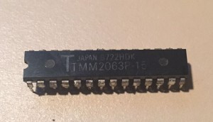
I dumped the main program ROMs and 2 out of the 3 matched the 1943ja set in MAME. I burned a replacement for the mismatch and tried it on the board but it made no difference. Without much else to go on I removed the main RAM (TMM2063) and installed a socket and replacement RAM – everything worked 100%! I replaced the original program ROM and it kept on working, so the RAM was the only fault.

IMG_4030IMG_4036

Let’s return to why the BM01 program ROM didn’t match the MAME set by disassembling them and comparing. Rather than find this is just random bit rot, there are 3 deliberate changes to the Z80 program code.

MAME set (1943ja)

0A7C: 3A 07 C0 ld a,($C007)
0A7F: B8 cp b
0A80: 18 17 jr $0A99

New set

0A7C: 3A 07 C0 ld a,($C007)
0A7F: B8 cp b
0A80: 28 17 jr z,$0A99

So in the new set, the program loads a byte from $c007, compares it to register b, then if equal jumps to location $0a99. In the MAME set, it loads the byte, compares it – then jumps regardless of the comparison. Why bother reading a byte and compare if you don’t care about the result? Well, this makes sense when you realise $c007 is the security protection device. The 1943ja program has clearly been patched to ignore whether the protection checks pass or fail. The new set is surely the pristine ‘original’. 1943ja has two other patches at $b02 and $281e that work the same way.

IMG_4039IMG_4025

By

MAME – ‘Color Space’ (Data East palettes)

Here’s an odd thing, I added a bunch of the mid-eighties Data East games to MAME around 1997-1999 – and just today realised the colors in many of them have been subtly wrong all this time.  In fact I suspect this might affect quite a lot of games in MAME.  The problem is a long-standing assumption that games with a palette RAM will emit a linear analog RGB signal proportional to the digital value.  But on the real hardware – many don’t.

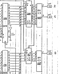
Games such as Karnov, Gondomania, Real Ghostbusters, etc, use 4 bits per color channel – these 4 digital bits then feed into a resistor network to create an analog signal for the RGB monitor, a simple DAC in other words.  For these games the resistor network is a 12pin custom Data East part marked RM-C3.  The values are 220 ohms (MSB), 470 ohms, 1 kohm, 2.2 kohm (LSB).

IMG_2445palette

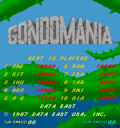
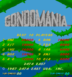
So, with those values it’s not actually a linear conversion – the high bit has slightly more weighting than you would expect, the low bits have slightly less.  The picture below shows how the colors actually should look when expanded to a 24 bit PC display.  Each column has the linear conversion on the left, and the corrected non-linear on the right.

test

Look, I said it was subtle :)

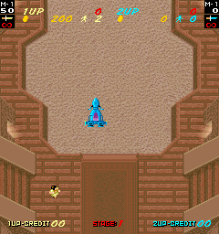
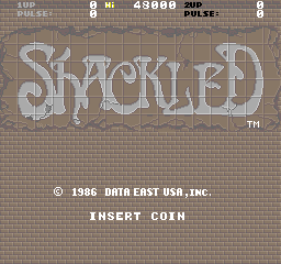
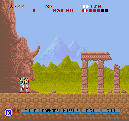
The in-game difference is subtle as well, but it’s there on the Gondomania gameplay ground, or the shadowed greens on the title screen.  Shackled looks a little more saturated.  Oscar a little more detail.  Ultimately this is a tiny change, but it does reflect the original hardware a little more which is what MAME is about.

00000000_new

00010001_new

00000000_new

00000000_new

00010001_new


By

Operation Wolf

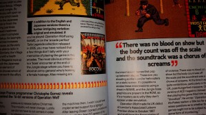
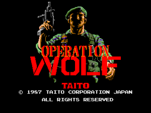
Recently RetroGamer ran a feature on Operation Wolf (Taito, 1987) that mentioned the emulation in M.A.M.E. and the ‘arcade perfect’ Taito Legends (PS2, 2005) was not quite correct – missing cutscenes, a missing boss, some other details.  Unfortunately, that’s true – the reason is Operation Wolf contains copy protection that has never been properly emulated.  I was the programmer who implemented the protection emulation on Taito Legends (PS2) and then M.A.M.E. and it’s actually based on a bootleg (pirate) version of the game.  The problem was that original ‘cracker’ of the game didn’t get everything right.  The protection device is actually an 8 bit micro controller of some sort that maps into 256 bytes of the main CPU address space.  It runs a private embedded program that cannot be read out, so what exactly the controller does is somewhat of a mystery.  Memory mapping is a very effective copy protection when done right, as the main CPU can just write bytes into random locations, and then expect certain results & logic back at a later date without any obvious link as to what inputs caused what outputs.  The bootleg sheds light on the setup though – one example is the end of level detection – the main cpu constantly writes the number of enemies, tanks & helicopters remaining in the level into shared memory.  Only when all of these are zero does the protection chip write a byte that signals ‘level is complete’.  The protection is effective because without a reference it’s very hard to know the internal logic of the controller.

20160325_185948

Prototype

By chance, a prototype Japanese version of Operation Wolf was recently discovered – this was almost certainly a test unit placed on location for player feedback before the game was finished, and before the copy protection was added.  It’s fairly close to the final game though, and does contain the missing scenes and boss, so in theory it should be possible to compare the two programs, and make a guess at what the protection logic is doing compared to the unprotected reference program.  I thought some people might like to read about this process, so hence this post – be warned, it’s going to get a bit technical…

0005

Initial Comparison

In an ideal world the two games would disassemble to near identical programs, with the only difference being a bit of protection logic replacing the original game logic from the prototype.  Unfortunately that’s not the case – what we can see is that there is a lot of code that is logically the same – but it’s assembled to different locations, and variables have moved around in memory.  Some of that is deliberate – with some variables moving into shared c-chip (protection) ram rather than main memory, but some of it is clearly just from sections being moved around in the original source and the assembler following suit.

00541E: 6100 0024 bsr $5444
005422: 3211 move.w (A1), D1
005424: 0241 8200 andi.w #$8200, D1
005428: 0C41 8000 cmpi.w #-$8000, D1
00542C: 660E bne $543c
00542E: 4251 clr.w (A1)
005430: 7200 moveq #$0, D1
005432: 1229 001F move.b ($1f,A1), D1
005436: 3F01 move.w D1, -(A7)
005438: 4E42 trap #$2
00543A: 548F addq.l #2, A7
00543C: D2C4 adda.w D4, A1
00543E: 51C8 FFE2 dbra D0, $5422
005442: 4E75 rts
006100: 6100 002C bsr $612e
006104: 3211 move.w (A1), D1
006106: 0241 8200 andi.w #$8200, D1
00610A: 0C41 8000 cmpi.w #-$8000, D1
00610E: 6616 bne $6126
006110: 48E7 8000 movem.l D0, -(A7)
006114: 4251 clr.w (A1)
006116: 7200 moveq #$0, D1
006118: 1229 001F move.b ($1f,A1), D1
00611C: 3F01 move.w D1, -(A7)
00611E: 4E42 trap #$2
006120: 548F addq.l #2, A7
006122: 4CDF 0001 movem.l (A7)+, D0
006126: D2C4 adda.w D4, A1
006128: 51C8 FFDA dbra D0, $6104
00612C: 4E75 rts
0119F8: 203C 4001 0306 move.l #$40010306, D0
0119FE: 3439 000F F036 move.w $ff036.l, D2 // current level
011A04: 0C02 0002 cmpi.b #$2, D2
011A08: 6700 0004 beq $11a0e
011A0C: 7000 moveq #$0, D0
011A0E: 3439 000F F04C move.w $ff04c.l, D2
011A14: 0242 00FF andi.w #$ff, D2
011A18: 08E9 0003 0000 bset #$3, ($0,A1)
011A1E: D5FC 0000 0010 adda.l #$10, A2
011A24: 6100 E5B8 bsr $ffde
011A28: 4E75 rts
00DD8C: 203C 4001 0306 move.l #$40010306, D0
00DD92: 0C6D 0002 0B20 cmpi.w #$2, ($b20,A5)
00DD98: 6700 0004 beq $dd9e
00DD9C: 7000 moveq #$0, D0
00DD9E: 142D 0C7D move.b ($c7d,A5), D2
00DDA2: 08E9 0003 0000 bset #$3, ($0,A1)
00DDA8: D5FC 0000 0010 adda.l #$10, A2
00DDAE: 6100 E834 bsr $c5e4
00DDB2: 4E75 rts

In the above tables the code functionally does the same thing but you can see it’s assembled to different addresses.  The original code (on the left) accesses the 8 bit c-chip shared ram for the level variable ($ffxxx), so it’s changed to byte instructions rather than word.

Software Architecture

Operation Wolf has interesting software architecture. Unlike most games of this
era which have a simple main loop and linear code flow, Operation Wolf
implements a co-operative threading model where routines run in 68K user mode
until giving up their timeslice and a supervisor mode scheduler picks the next
thread to run. There are 32 thread slots, and each enemy in game run as its
own thread/object as well as a thread for coins, scrolling the level, level
specific gameplay and so on. The code is very robust when creating threads,
for example if there are no free slots, the creating thread just spins until
a slot frees up. The rest of the game just keeps on playing in the background.
Another interesting detail is that a thread can give up it’s timeslice for more
than 1 frame – this makes it really easy to implement timed events. The ‘WARNING’
text at the end of level 2 is handled by a thread that prints to screen, then just
waits a second before spawning the boss enemy thread.

0015

Each level in the game implements its own logic thread and often sub-threads -
this is the major difference between the protected game and the bootleg – the bootleg
mostly implements the parts that are generic between all levels rather than all of
the details. The biggest single area the bootleg did not implement revolves
around location 0x5f in the shared c-chip RAM. The original code sets up a thread
that just waits for this value to become non-zero. It then jumps to a set of
functions defined in a look-up table (that can then spawn further threads). There
are 10 non-null functions tied to this routine.
 
1: Enemy spawn for level 7 (first ‘Located’ cut-scene)

2: Enemy spawn for level 8 (second ‘Located’ cut-scene) – zoom in helicopters

3: Enemy spawn for level 9 (third ‘Located’ cut-scene)

4: Boss & hostage sequence for level 2

5: Enemy spawn when less than 45 enemies in level 2 (paratrooper drop-down)

6: Enemy spawn when less than 25 enemies in level 2

7: Enemy spawn when 0 men left in levels 2,4,5,6

8: Enemy spawn when 0 men left in level 3

9: Enemy spawn when 0 men left in level 1

10: Special explosion animation when level 4 (Powder Dump) is completed


The bootleg also misses some other details, for example in level 5 the c-chip
sets a flag when all men are destroyed (not vehicles) and this triggers the 68K
to scroll the screen vertically to focus on the remaining helicopter enemies.

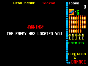
The ‘Enemy has located you’ cut-scenes appear ‘randomly’ between levels in the
original game, but are deliberately disabled in the bootleg. The exact formula
for determining if the cut-scene appears is ‘(frameCount & levelNumber)==0′.  There are three different cutscene levels.


0012

Source Dumps

Should you want to see what the code for an old arcade game looks like I’ve attached my annotated dumps of the original and prototype source code – it fills in some labels and some variables and the thread functions to make it easier to read!


_signal_end_of_level:
0053EC: 322D 0B20 move.w $CURRENT_LEVEL, D1
0053F0: 0C41 0006 cmpi.w #$6, D1
0053F4: 6614 bne $540a
0053F6: 1B7C 0001 0998 move.b #$1, ($998,A5)
0053FC: 4EB9 0000 3314 jsr $3314.l
005402: 3F3C 0020 move.w #$20, -(A7)
005406: 4E46 trap #$6 (SLEEP_THREAD_FOR_N_FRAMES)
005408: 548F addq.l #2, A7
00540A: 6100 0012 bsr $541e
00540E: 3F3C 003C move.w #$3c, -(A7)
005412: 4E46 trap #$6 (SLEEP_THREAD_FOR_N_FRAMES)
005414: 548F addq.l #2, A7
005416: 1B7C 0001 0999 move.b #$1, $END_OF_LEVEL_FLAG 
00541C: 4E45 trap #$5 (KILL_THREAD)

opwolf.dasm  opwolfp.dasm

00040008

By

Fighters History protection chip

I found an interesting project on a backup harddrive from 2002 which was the ‘Trojan horse’ software I wrote to analyse the software protection device on the Data East Fighters History arcade pcb game.

I doubt the code itself is very useful anymore but the process it used may still be interesting.  You can download the files >here

fh2fh3

FH used an ARM cpu – ARM cpus are everywhere these days but were still quite rare in 1993!  Coupled to this was a copy protection chip that essentially had a range of input ports the CPU could write to and modified results could be read back.  By writing game code variables to the chip and the code that read them back ‘knowing’ the permutation that would be applied the copy protection was quite effective.  Unless you knew all the hardware permutations game code would at worst crash and at best behave incorrectly – drawing wrong graphics, game moves not working correctly, etc.  Because it was close to impossible to guess what the protection chip did just by examining the software the only solution is to run special software on the board that deliberately probes the protection device by writing known values and examining the results returned.  Hence ‘Trojan horse’.

Unlike earlier 8 and 16 bit games it was actually feasible to use a modern C compiler to write code to run on this device, so the official ARM c compiler was used (circa 2000) and the flow was C program -> .o ASM file -> patch ASM into original ROM image -> split ROM image into 2 16 bit images -> burn ROMs to EEPROM -> install EEPROMs on board -> get results!

The main components on the pcb board below are A – the ARM cpu (not marked as ARM – they only licensed the design so the chip was fabricated for Data East and is marked as such).  B – two 16 bit program EEPROMs – the 16 bit data buses are interleaved to provide a 32 bit stream for the CPU.  C – the protection chip itself.  The fact it’s mounted on a daughterboard suggests it was added to the hardware design fairly late.

fh


Recently I noticed Charles Macdonald had furthered the work I done on this – http://cgfm2.emuviews.com/new/detech.txt


By

VCMame

VCMame archive project has been added – this allowed the use of Visual Studio 6 and Visual Studio .NET to build and debug the MAME project as opposed to the standard GCC/GDB/makefile command line setup.

http://www.bryanmcphail.com/vcmame/