BryanMcPhail.com

Professional software development, amateur BMW tinkering, old arcade game stuff

By

Super Chase / Hantarex Polo

A reasonably rare/overlooked game from Taito in 1992. This was completely dead when I got it – no lights, sounds, picture. The power supply was the first problem as it wasn’t able to supply +5V to the pcb. In fact I had to try 3 (used) power supplies until I found one that could give a consistent +5. This pcb draws a lot more current than a lot of older titles (probably as it uses a 68020 CPU and two sub 68000 cpus, plus a lot of graphics and sound ic’s that were cutting edge at the time) so some power supplies can’t keep up and voltage drops.

IMG_0234 IMG_0251

This made two LED’s on the light driver board illuminate, but still nothing else. The sound board is quite unusual in it expects +13V as well as +5V and +12V. Without the +13V line connected the sound amps don’t work at all – however putting 12V there made them work well enough that I could hear game sounds – so pcb confirmed as running! [I should mention that Super Chase isn't jamma - so I couldn't just test it in another cabinet].

The monitor remained completely dead – it’s a Hantarex Polo 25″ standard resolution. No signs on physical problems (cold solder joints, blown fuses, burnt areas, broken components). I hate working on high voltage stuff, so rather than debug anything I decided just to shotgun replace the flyback, all capacitors, and the HOT (horizontal output transistor). On a 23 year old monitor it’s a good bet the capacitors need replacing, and the flyback may have failed. Internet repair logs on this monitor suggest bad flybacks can kill the HOT, so as it’s only $5 may as well replace it too.

IMG_0250 IMG_0249

And it worked! It’s quite unusual for a cap kit to bring a dead monitor back to life, but the Polo has a built in power supply (no isolation transformer needed) so bad caps there were probably the primary reason for not turning on. Monitor looks good as new now.

A cool thing about Super Chase is the flashing lights – these are just 40W incandescent bulbs, but both were blown – replaced them, and replaced a blown fuse on the driver board and all was good there. The driver board is quite a simple thing – it takes two 5V lines from the game pcb as input, a 110V mains source, and outputs two 110V lines to the bulbs. You can see the board is designed for 4 lights, but only 2 channels are populated.

IMG_0264 IMG_0262

(Main marquee light still not fixed in picture below)

IMG_0268IMG_0278 IMG_0275


By

Operation Wolf

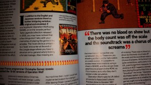
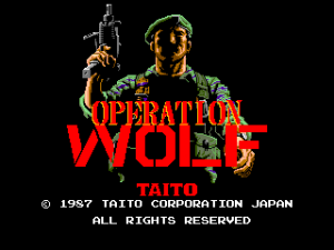
Recently RetroGamer ran a feature on Operation Wolf (Taito, 1987) that mentioned the emulation in M.A.M.E. and the ‘arcade perfect’ Taito Legends (PS2, 2005) was not quite correct – missing cutscenes, a missing boss, some other details.  Unfortunately, that’s true – the reason is Operation Wolf contains copy protection that has never been properly emulated.  I was the programmer who implemented the protection emulation on Taito Legends (PS2) and then M.A.M.E. and it’s actually based on a bootleg (pirate) version of the game.  The problem was that original ‘cracker’ of the game didn’t get everything right.  The protection device is actually an 8 bit micro controller of some sort that maps into 256 bytes of the main CPU address space.  It runs a private embedded program that cannot be read out, so what exactly the controller does is somewhat of a mystery.  Memory mapping is a very effective copy protection when done right, as the main CPU can just write bytes into random locations, and then expect certain results & logic back at a later date without any obvious link as to what inputs caused what outputs.  The bootleg sheds light on the setup though – one example is the end of level detection – the main cpu constantly writes the number of enemies, tanks & helicopters remaining in the level into shared memory.  Only when all of these are zero does the protection chip write a byte that signals ‘level is complete’.  The protection is effective because without a reference it’s very hard to know the internal logic of the controller.
20160325_185948

Prototype

By chance, a prototype Japanese version of Operation Wolf was recently discovered – this was almost certainly a test unit placed on location for player feedback before the game was finished, and before the copy protection was added.  It’s fairly close to the final game though, and does contain the missing scenes and boss, so in theory it should be possible to compare the two programs, and make a guess at what the protection logic is doing compared to the unprotected reference program.  I thought some people might like to read about this process, so hence this post – be warned, it’s going to get a bit technical…
0005

Initial Comparison

In an ideal world the two games would disassemble to near identical programs, with the only difference being a bit of protection logic replacing the original game logic from the prototype.  Unfortunately that’s not the case – what we can see is that there is a lot of code that is logically the same – but it’s assembled to different locations, and variables have moved around in memory.  Some of that is deliberate – with some variables moving into shared c-chip (protection) ram rather than main memory, but some of it is clearly just from sections being moved around in the original source and the assembler following suit.

00541E: 6100 0024 bsr $5444
005422: 3211 move.w (A1), D1
005424: 0241 8200 andi.w #$8200, D1
005428: 0C41 8000 cmpi.w #-$8000, D1
00542C: 660E bne $543c
00542E: 4251 clr.w (A1)
005430: 7200 moveq #$0, D1
005432: 1229 001F move.b ($1f,A1), D1
005436: 3F01 move.w D1, -(A7)
005438: 4E42 trap #$2
00543A: 548F addq.l #2, A7
00543C: D2C4 adda.w D4, A1
00543E: 51C8 FFE2 dbra D0, $5422
005442: 4E75 rts
006100: 6100 002C bsr $612e
006104: 3211 move.w (A1), D1
006106: 0241 8200 andi.w #$8200, D1
00610A: 0C41 8000 cmpi.w #-$8000, D1
00610E: 6616 bne $6126
006110: 48E7 8000 movem.l D0, -(A7)
006114: 4251 clr.w (A1)
006116: 7200 moveq #$0, D1
006118: 1229 001F move.b ($1f,A1), D1
00611C: 3F01 move.w D1, -(A7)
00611E: 4E42 trap #$2
006120: 548F addq.l #2, A7
006122: 4CDF 0001 movem.l (A7)+, D0
006126: D2C4 adda.w D4, A1
006128: 51C8 FFDA dbra D0, $6104
00612C: 4E75 rts
0119F8: 203C 4001 0306 move.l #$40010306, D0
0119FE: 3439 000F F036 move.w $ff036.l, D2 // current level
011A04: 0C02 0002 cmpi.b #$2, D2
011A08: 6700 0004 beq $11a0e
011A0C: 7000 moveq #$0, D0
011A0E: 3439 000F F04C move.w $ff04c.l, D2
011A14: 0242 00FF andi.w #$ff, D2
011A18: 08E9 0003 0000 bset #$3, ($0,A1)
011A1E: D5FC 0000 0010 adda.l #$10, A2
011A24: 6100 E5B8 bsr $ffde
011A28: 4E75 rts
00DD8C: 203C 4001 0306 move.l #$40010306, D0
00DD92: 0C6D 0002 0B20 cmpi.w #$2, ($b20,A5)
00DD98: 6700 0004 beq $dd9e
00DD9C: 7000 moveq #$0, D0
00DD9E: 142D 0C7D move.b ($c7d,A5), D2
00DDA2: 08E9 0003 0000 bset #$3, ($0,A1)
00DDA8: D5FC 0000 0010 adda.l #$10, A2
00DDAE: 6100 E834 bsr $c5e4
00DDB2: 4E75 rts

In the above tables the code functionally does the same thing but you can see it’s assembled to different addresses.  The original code (on the left) accesses the 8 bit c-chip shared ram for the level variable ($ffxxx), so it’s changed to byte instructions rather than word.

Software Architecture

Operation Wolf has interesting software architecture. Unlike most games of this
era which have a simple main loop and linear code flow, Operation Wolf
implements a co-operative threading model where routines run in 68K user mode
until giving up their timeslice and a supervisor mode scheduler picks the next
thread to run. There are 32 thread slots, and each enemy in game run as its
own thread/object as well as a thread for coins, scrolling the level, level
specific gameplay and so on. The code is very robust when creating threads,
for example if there are no free slots, the creating thread just spins until
a slot frees up. The rest of the game just keeps on playing in the background.
Another interesting detail is that a thread can give up it’s timeslice for more
than 1 frame – this makes it really easy to implement timed events. The ‘WARNING’
text at the end of level 2 is handled by a thread that prints to screen, then just
waits a second before spawning the boss enemy thread.

0015

Each level in the game implements its own logic thread and often sub-threads -
this is the major difference between the protected game and the bootleg – the bootleg
mostly implements the parts that are generic between all levels rather than all of
the details. The biggest single area the bootleg did not implement revolves
around location 0x5f in the shared c-chip RAM. The original code sets up a thread
that just waits for this value to become non-zero. It then jumps to a set of
functions defined in a look-up table (that can then spawn further threads). There
are 10 non-null functions tied to this routine.
 
1: Enemy spawn for level 7 (first ‘Located’ cut-scene)

2: Enemy spawn for level 8 (second ‘Located’ cut-scene) – zoom in helicopters

3: Enemy spawn for level 9 (third ‘Located’ cut-scene)

4: Boss & hostage sequence for level 2

5: Enemy spawn when less than 45 enemies in level 2 (paratrooper drop-down)

6: Enemy spawn when less than 25 enemies in level 2

7: Enemy spawn when 0 men left in levels 2,4,5,6

8: Enemy spawn when 0 men left in level 3

9: Enemy spawn when 0 men left in level 1

10: Special explosion animation when level 4 (Powder Dump) is completed


The bootleg also misses some other details, for example in level 5 the c-chip
sets a flag when all men are destroyed (not vehicles) and this triggers the 68K
to scroll the screen vertically to focus on the remaining helicopter enemies.

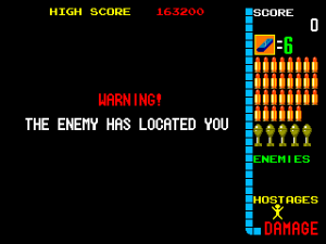
The ‘Enemy has located you’ cut-scenes appear ‘randomly’ between levels in the
original game, but are deliberately disabled in the bootleg. The exact formula
for determining if the cut-scene appears is ‘(frameCount & levelNumber)==0′.  There are three different cutscene levels.
 

0012

Source Dumps

Should you want to see what the code for an old arcade game looks like I’ve attached my annotated dumps of the original and prototype source code – it fills in some labels and some variables and the thread functions to make it easier to read!


_signal_end_of_level:
0053EC: 322D 0B20 move.w $CURRENT_LEVEL, D1
0053F0: 0C41 0006 cmpi.w #$6, D1
0053F4: 6614 bne $540a
0053F6: 1B7C 0001 0998 move.b #$1, ($998,A5)
0053FC: 4EB9 0000 3314 jsr $3314.l
005402: 3F3C 0020 move.w #$20, -(A7)
005406: 4E46 trap #$6 (SLEEP_THREAD_FOR_N_FRAMES)
005408: 548F addq.l #2, A7
00540A: 6100 0012 bsr $541e
00540E: 3F3C 003C move.w #$3c, -(A7)
005412: 4E46 trap #$6 (SLEEP_THREAD_FOR_N_FRAMES)
005414: 548F addq.l #2, A7
005416: 1B7C 0001 0999 move.b #$1, $END_OF_LEVEL_FLAG 
00541C: 4E45 trap #$5 (KILL_THREAD)

opwolf.dasm  opwolfp.dasm

00040008

By

Pacland PCB repair

After making a custom loom for this untested pcb, I found it booted to garbage. Booting to garbage is at least better than not booting at all though as it shows the video output section is at least running.  After checking the voltages at the chips were 5V (or slightly higher) and that the program eproms I examined other socketed chips and found the custom chip 34 had badly corroded pins when removed from the socket, and a few of the legs snapped completely.


Repair 1 – clean up the corrosion and mount the chip in a new socket and solder through from the broken pins to the socket top. Not the prettiest fix but it works.


Unfortunately, this didn’t change much with regards the corruption. So I put a logic probe on the CPU and found the clock pins (Q & E) and the address and data bus pins had activity on them. However, the read/write pin seemed stuck high – this means the CPU could only be reading from RAM, never writing to it and a CPU that can’t write data certainly can’t run properly. The CPU also got very hot very quickly.

Theory 1 – CPU has failed internally, and R/W has stuck high.
Theory 2 – the chip the R/W pin connects to has failed and forced the R/W line high regardless of what the CPU tries to do.

The CPU is in a socket so that’s the easiest thing to try first – however I didn’t own others of this type to swap in (HD6309, slightly different from regular M6809) so had to wait a week to order some from Ebay.

And.. didn’t help, no change. The R/w pin connects to an LS368 chip at location 5A and suspiciously it has corroded pins, even though all the chips around it are perfect. So remove and replace that.

And.. still corruption, though it’s different and it seems the CPU is definitely doing ‘something’ as the corruption cycles a few times before stopping. In retrospect I think the stuck R/w pin theory was a bit flawed – if it was truly stuck then the corruption would probably be random each time, and this was consistent. Instead more likely the CPU started to run the program then just parked itself in an infinite read loop when it detected a failure.  The LS368 was probably bad in some other way though.

So Pacland in MAME shows that on boot the game should print 0 0 0 on screen to show all self-tests passed.  The curious thing about the new corruption is you could clearly see the screen clear a few times then a couple of zeros appeared, just not where you would expect them to be.

So new theory – RAM is bad – as when the CPU tries to write the zero character it gets reflected in a bunch of other locations (so the internal address decoding has failed).  So, desolder and test the 7 6116 RAM chips on the top right of the board.  The top 4 is the RAM for the tile maps, the bottom 3 is for the sprites and CPU workram.

Unfortunately, all the RAM tested good.  So..  time to examine the schematics to see what is in-between the RAM and the CPU.  I desoldered the IC’s at 10B, 9E, 9D, 10N, 9F – these control the enable lines to the RAM.  All tested good so no progress.

Usually in arcade schematics you read from left to right – inputs on the left, and outputs on the right.  There’s an exception in Pacland though, as the tile map ram chips can be addressed by the main CPU, or by the graphics hardware through a custom chip.  So the address bus on the right of the RAM in the schematics is actually an input, and it comes from a pair of LS365 chips.  These chips seems relatively rare on arcade pcbs, and my tester doesn’t support them.  Their use seems to be in allowing both the CPU and graphics hardware access to the RAM chips.  This is driven by the 2H signal – from the name I assume it toggles twice for every horizontal pixel – so for every pixel on the screen both the CPU and graphics get RAM access.

Switched these chips out for new – and instantly no more corruption!  The 0 0 2 self test signals bad RAM, but this was expected as I hadn’t replaced the sprite ram at this point.

In game however, corruption remained on the backgrounds, but at least sprites and logic were working 100%!  Time to look at the video part of the schematics which I’d mostly ignored until now.  Custom chip 36 makes the tile maps.  It has access to the tile map ram of course, two eproms with graphics data, and two color proms.  We know the tile map RAM itself is good, so time to test the LS174 and LS86 chips that drive addressing to the graphics eprom.  Unfortunately all tested good, so the problem wasn’t there.

Tracing back further shows a LS365 and LS366 involved in addressing the tile map ram from the graphics side (NOT used by the CPU side access).  Really I should have tested them first as having already found a bad LS365 there’s a good chance another from the same batch would have failed in the same way.  Replaced these and everything was good!


Time taken : > 10 hours over 3 weeks (lots of waiting for parts to arrive)

By

Rastan PCB repair

Ok, calling this is a ‘repair’ is probably a misrepresentation as it was so easy. I bought this pcb from a junk pile and it arrived a bit dusty but not physically damaged in any way. It was missing all eproms (68K program, Z80 audio program, audio samples eprom) and the socketed PAL at IC58 (PAL16L8). The schematics show that IC58 generates monitor sync so it definitely wasn’t going to show anything without that..

Burned all eproms from the MAME set, and the PAL16L8 onto a GAL with thanks to the PLD images at http://www.jammarcade.net/pal-dumps/

And it worked! Well, almost – no sound and wouldn’t accept any coins. It seems this is due to the connector marked H on the board. I’d assumed this was a stereo sound output, but it seems 12V is required here in order to power the sound amp and coin IO. 12V from the jamma connector already runs here – so you have to jumper pins 1 & 2 together and 3 & 4 together to enable sound & coins. With this done the game worked fine.

Mystery 1 – why does connector H even exist, when 12V is already at the jamma connector!?
Mystery 2 – why did an operator strip a (presumably) working board just for some cheap eproms and a PAL? I guess something else more important at the time needed the parts.