BryanMcPhail.com

Professional software development, amateur BMW tinkering, old arcade game stuff

By

Data East Crude Buster (Two Crude) arcade PCB repair

This is actually a pcb from the UKVac ‘Kent Raid’ (see https://arcadeblogger.com/2016/12/16/arcade-raid-cabs-found-in-kent-uk/), interesting to know the history of a pcb and this one sat abandoned for over 20 years.

IMG_1601

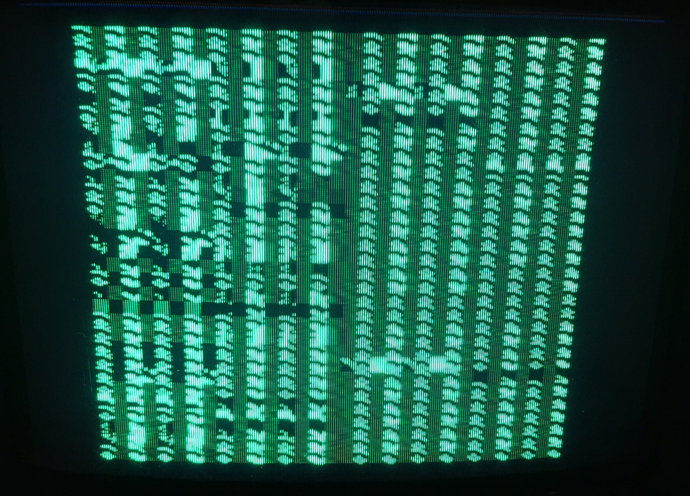
When powered on green garbage was displayed and that’s about it – no signs of life.  I tested the main RAM with a logic probe – the address pins were pulsing, as were the write enable and output enable pins, but the data lines remained stuck.  That’s a good sign the CPU is trying to do something but the RAM is dead – so I replaced the two chips (64K sram – TMM2063) with another two from a parts board.  Now I had some corrupt movement on screen, but it was also consistent corruption on every boot, so I was hopeful the game logic was actually running underneath the corruption.

IMG_1602IMG_1605

Probing some more RAM chips in the same way revealed two dead 16K sram chips – these are the red and blue palette RAMs – so replacing them game full colour corruption.  The audio CPU RAM appeared ok with the logic probe, but when I piggy-backed another 64K sram on top and hit the coin switch sound & music played, so I knew for sure the audio RAM was bad, but also the main CPU was running properly now.

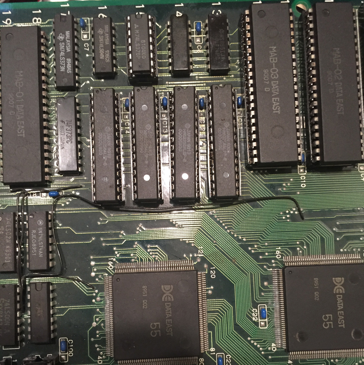
Logic probe on the 4 ram chips near the custom tilemap asic showed address and data lines pulsing, but after removing them from the board they all tested bad.  At this point I had no 64K sram left so I removed 4 256K srams from a dead Run N Gun board and used them instead.  The pinouts between 64K and 256K are identical except for the extra 2 address lines – so as long as you make sure these lines are tied high or low it will work (I soldered little jumper wires onto the bottom of the board to tie the lines high).  Success – all tilemap graphics now working, but still no sprites.

With all the other bad RAM on the board, bad spriteram was likely – many Data East games actually have a setup where there are two copies of spriteram.  The main CPU writes to one set, then when complete sets a flag for hardware to copy it to the second set, that the sprite ASIC reads out of.  I assume the reason for this design was to avoid contention between the CPU writing and the ASIC reading the same memory.  All chips tested bad when removed from the board.  When replaced sprites came back, but were obviously corrupt.

IMG_1705 IMG_1721 IMG_1656

At this point I spent quite a lot of time triple checking all points I’d soldered on the new RAM, then checking for bad pins on the sprite ASIC, or any problems in the TTL that copies between the two spriterams.  It’s clear the player sprite was ‘almost’ correct, but had a corrupt layer on top of it. Eventually I unsoldered the large sprite mask ROMs to check if they were corrupt, but the checksums matched the MAME set.  When I booted the board with those ROMs missing though, the corrupt bit planes remained and suddenly it was clear what was going on.  The output enables for the second set of sprite roms were all stuck on – so whenever the main ROMs were active data from the second set was superimposed on top.  The custom sprite ASIC (chip 52) has a 32 bit combined data and address bus.  On one cycle it latches the desired address into external TTL, then on the next cycle it activates the sprite ROMs to read 32 bits of data.  The TTLs for the lower 16 address bits were fine, but the top 4 bits are controlled by a Fujitsu LS375N which had stuck outputs when tested with the logic probe.  This chip was replaced and all sprites were correct.

IMG_2069 IMG_1800 IMG_1797 IMG_1792


By

Technos WWF Superstars arcade PCB Repair

Two different boards, both very clean with no physical damage.  One booted to corruption, the other to a solid white screen.  Logic probe showed the outputs on the palette RAM were dead on the second board, so when replaced it also booted to corruption like the first one.

Piggy back on palette RAMIMG_1751

The logic probe seemed to the show the 68000 CPU was not getting a clock signal so I probed the chips near the crystal oscillator and removed them from the board with a heat gun for external testing (but they tested fine).  Strangely the game worked when I replaced the chip – that’s good but why?  I then also found the second board would sometimes boot if I flexed the PCB near the crystal.  My only theory is bad solder joints on the crystal that were fixed when the heat gun was used.  The second board also boots consistently after re-doing the solder around the crystal even though it looked fine.

IMG_1732 IMG_1747

So board 1 now works 100% with sound.  Board 2 boots but had some doubled up sprites at first (fixed by reseating the connectors between the two layers) and no sound.  The sound amp seems to be working, but at least one problem seems to be the YM3014 DAC chip.  The logic probe shows pulsing on the digital inputs, but the voltmeter shows no movement on the analog outputs (unlike the working board).  Right now I don’t have a spare to check.

IMG_1755 IMG_1759 IMG_1764


By

Atari Asteroids / Wells 19V2000 HV Diode

There’s a wealth of information on old black & white vector monitors on the internet, so when the picture on my Asteroids ‘bloomed’ up much larger than it should be and became unstable I quickly found tips suggesting the high voltage diode was at fault.  However.. most of this information was actually written in Usenet times – text only documents!  I couldn’t actually find a picture anywhere of where this diode is.

So for anyone else searching, I’ve circled it in red in the photo.  I used a diode marked ‘VARO H598′ bought from Ebay which is not the original part, but comes recommended as a replacement, and indeed it works perfectly.

I should also point out you should make sure the monitor CRT is fully discharged before going near this part as the high voltage can be present even when the monitor is powered off.  Info on that can be found elsewhere on the internet.

IMG_1269 IMG_1270 IMG_1272IMG_1291


By

Midnight Resistance arcade cabinet restore

Cab wasn’t terrible when I got it – two chunks of wood missing, lot of mold and dust, but the wood and vinyl fundamentally ok, so I decided to paint it rather than re-apply vinyl or laminate.

IMG_1417 IMG_1419


Tried out ‘wood’ Bondo rather than regular Bondo to patch up scuffs and missing pieces.  I used some spare t-molding as a guide to fill the missing chunk at the control panel, worked out quite well.  Also filled in the holes from those big ugly lock bars, not putting them back on.

IMG_1503 IMG_1502

Some painting, then sanding, then more painting..  Plus new t-molding all-around, and replaced faded marquee with a reproduction.

IMG_1568

I swapped out the plain joystick tops with some burn marks for some Data East logo tops I’ve had sitting around for a while.  They aren’t perfect but better.

IMG_1590

Reproduction control panel overlay added and NOS side-art that I’ve been hoarding for a while.  Original bezel remains even though it has some stains and a rip.  Might change it out later.

IMG_1591 IMG_1569

Coin door was fully disassembled, some rust cleaned up, repainted and new locks added.

IMG_1831

End result!  It’s not a 10/10 maybe an 8 out of 10, but good enough :)

IMG_1842