BryanMcPhail.com

Professional software development, amateur BMW tinkering, old arcade game stuff

By

MAME – ‘Color Space’ (Data East palettes)

Here’s an odd thing, I added a bunch of the mid-eighties Data East games to MAME around 1997-1999 – and just today realised the colors in many of them have been subtly wrong all this time.  In fact I suspect this might affect quite a lot of games in MAME.  The problem is a long-standing assumption that games with a palette RAM will emit a linear analog RGB signal proportional to the digital value.  But on the real hardware – many don’t.

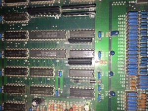
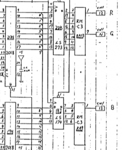
Games such as Karnov, Gondomania, Real Ghostbusters, etc, use 4 bits per color channel – these 4 digital bits then feed into a resistor network to create an analog signal for the RGB monitor, a simple DAC in other words.  For these games the resistor network is a 12pin custom Data East part marked RM-C3.  The values are 220 ohms (MSB), 470 ohms, 1 kohm, 2.2 kohm (LSB).

IMG_2445palette

So, with those values it’s not actually a linear conversion – the high bit has slightly more weighting than you would expect, the low bits have slightly less.  The picture below shows how the colors actually should look when expanded to a 24 bit PC display.  Each column has the linear conversion on the left, and the corrected non-linear on the right.

test

Look, I said it was subtle :)

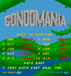
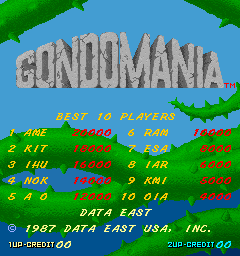
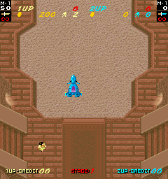
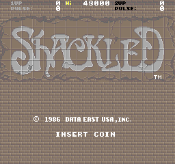
The in-game difference is subtle as well, but it’s there on the Gondomania gameplay ground, or the shadowed greens on the title screen.  Shackled looks a little more saturated.  Oscar a little more detail.  Ultimately this is a tiny change, but it does reflect the original hardware a little more which is what MAME is about.

00000000_new

00010001_new

00000000_new

00000000_new

00010001_new


By

Konami Rush’N Attack arcade pcb repair

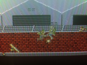
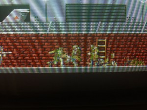
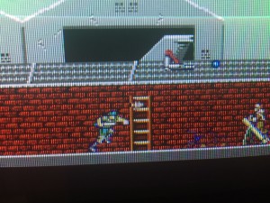
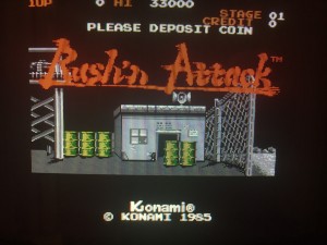
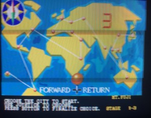
This pcb was in clean shape but sprites were corrupt.  It’s not very clear on the picture but it seemed every second column on the screen was missing, so was more likely to be in the sprite processing area than the ROMs (if it were the ROMs the missing lines would move around).
IMG_3126IMG_3125

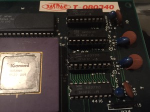
I confirmed the 4 RAM chips on the top right of the board near the graphics chip involved sprites by temporarily shorting some data lines together and watching the corruption change.  I was reasonably sure one of these chips was the problem, but a logic probe showed no obvious errors, so I removed them one by one and replaced with RAM from a parts boards.

The second chip from the top was the problem – replacing fixed the error!

IMG_3147 IMG_3149 IMG_3150


By

SNK NeoGeo 4 slot arcade pcb repair #2

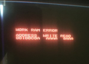
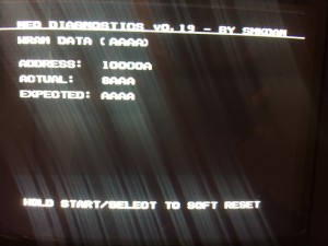
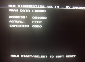
Another 4 slot – a previous owner had installed a new battery and replaced the palette RAM.  The board now reported a RAM error with the original BIOS, and the diagnostic ROM confirmed it as the upper WRAM chip (see my previous 4 slot repair).

IMG_3055 IMG_3059

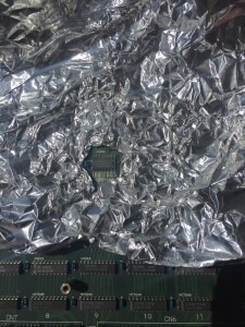
If you don’t have a SMT desolder station then (if you dare) you can remove surface mount chips with a heat-gun and some tinfoil to protect the surrounding areas.  The chips are capable of taking quite a lot of heat so the only worry is warping the board rather than damaging a chip.  Because there’s very little solder holding the SMT chips on though, they come off quite easily.

IMG_3063IMG_3062

With that one RAM chip replaced, everything worked!

IMG_3065


By

SNK NeoGeo 2 slot arcade pcb repair #2

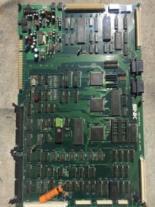
This Neo 2 slot was stuck constantly resetting, which means the 68000 CPU is not resetting the watchdog timer, so the board continually tries to reboot itself.  A previous owner had clearly changed out some faulty surface mount RAM previously so I spent some time verifying all data and address lines from RAM/ROM to the CPU were correct as some looked like they could be shorted.  Turned out fine however.  Without much more to go on I tried out the diagnostic ROM which surprised me by booting and showing a VRAM error.  In this case both of the 6116 fast vram type chips that often go bad.  Both chips desoldered, sockets added and replacements fitted.  Now the diagnostic ROM reported no faults, but the board kept on resetting with the original ROM installed.

IMG_3045 IMG_3023

IMG_3043

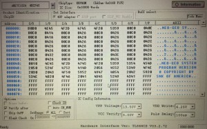
I dumped the original ROM and found it to be corrupt – no wonder the CPU kept crashing – really I should have tested that first.  Some kind of internal addressing fault as in the dump you can see some ASCII text where the reset and stack vectors should be.  Unibios was burned to a replacement eprom and everything worked again!

IMG_3048IMG_3049

IMG_3050

By

SNK NeoGeo 2 slot arcade pcb repair

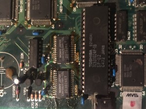
This NeoGeo 2 slot booted to a screen saying Z80 error.  That doesn’t necessarily mean the CPU is at fault – it could be the program ROM, the RAM or several intermediate chips that connect the Z80 to the main 68000 CPU that prints the error.  In this case though a logic probe seemed to show the Z80 was dead.  Desoldered, installed a socket and Z80 pulled from an Arkanoid, and everything worked!

IMG_2986 IMG_3013 IMG_3015 IMG_3016


By

Capcom Buster Bros / Pang arcade pcb repair

An original Capcom/Mitchell Buster Bros pcb booted to a solid blue-green screen.  This is one of the infamous suicide battery pcb’s, where a custom Z80 CPU contains a decryption table in volatile RAM powered by a battery.  When the battery dies the decryption table is lost and the program code cannot be run.  This pcb was an untouched original with a 29 year old battery, so safe to say the battery was stone dead.

IMG_2701

Full info on restoring these dead CPU’s can be found here – http://www.arcadecollecting.com/dead/pre-cps.html

One of the original tricks of this encryption is that program opcodes (instructions) are treated differently from operands (data).  This means that even if you understand the decryption and have the key you can’t just burn a new ROM in place as each byte the ROM will have two values depending if the CPU accesses it as data or instruction.  The solution is to decrypt the ROM for both data & instruction separately and burn to a new double size ROM with data in top half, instructions in lower half.  The CPU pin that controls whether instructions or data is being fetched is then used to select the upper address line on the ROM.

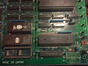
So the desuicide process is fairly simple – use 27c020 and 27c512 eproms to replace the originals, and run a wire to control the top address bit.  I’m pleased to say it booted up first time when I tried it.

IMG_2702IMG_2703

But..  pretty obvious there was no red color channel.  The palette RAM would be the first port of call in this situation, but a logic probe showed neither of the two chips had any stuck bits.  I probed down stream of the RAM and there are 3 LS367 chips.  One each for red, green and blue.  These are the last TTL chips before the signal is converted to the analog output and they control the blanking by cutting out the signal during h-blank and v-blank events.  Shorting pins 2 & 3 on the red channel chip fixed the problem and isolated the fault to that TTL chip (which is a strange type of failure but there you go).

IMG_2721IMG_2715