BryanMcPhail.com

Professional software development, amateur BMW tinkering, old arcade game stuff

By

Konami Iron Horse arcade pcb repair

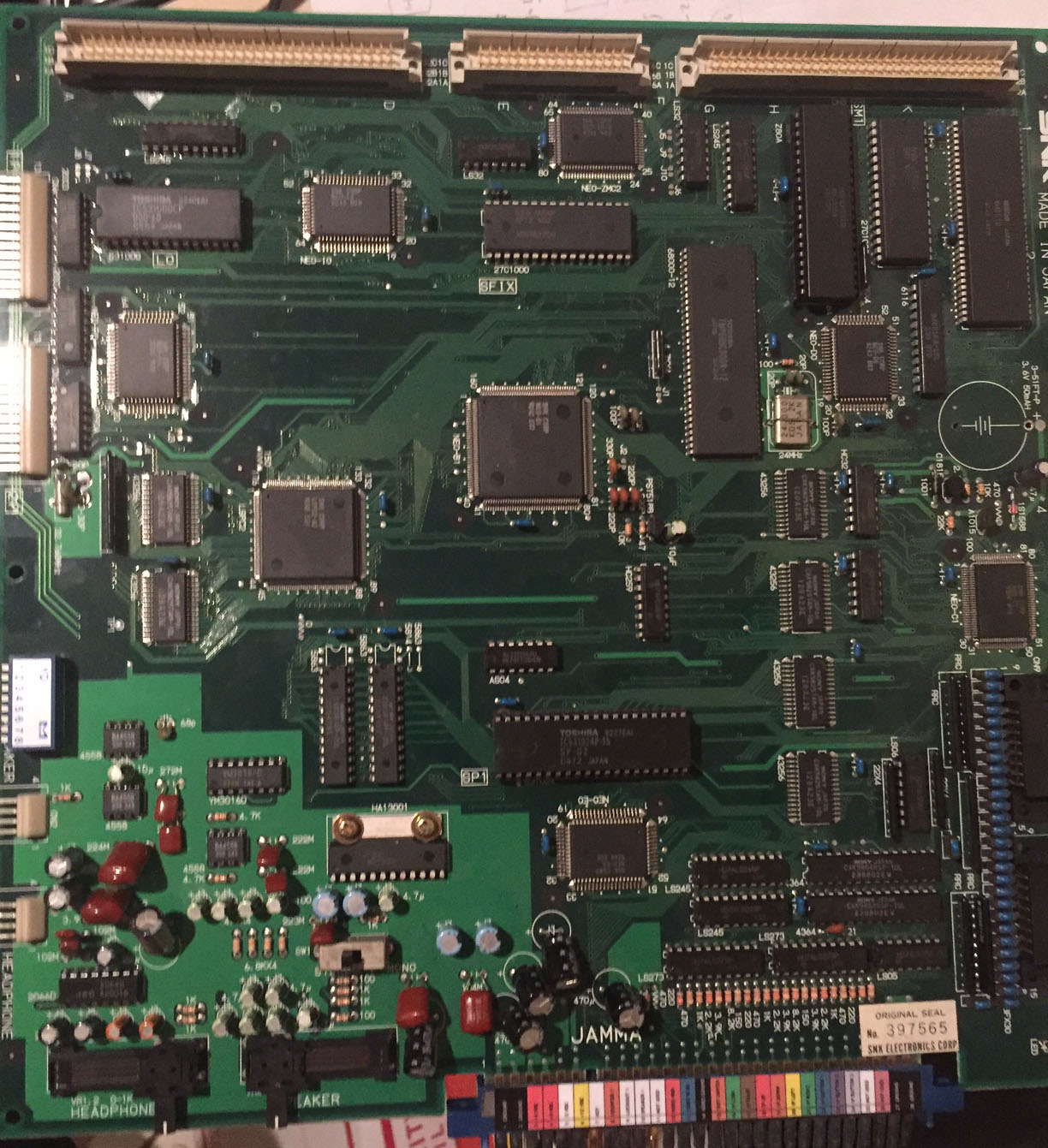
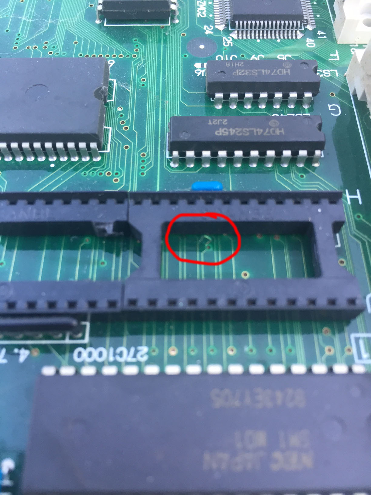
Terrible corrosion on this pcb, in fact all of the ROMs disintegrated on removal so new ROMs were burned and some sockets replaced.  With that done the pcb still only booted to garbage on screen and constant watchdog resets.  Watchdog resets usually mean the CPU program isn’t running.  On this board the watchdog can be disabled by bridging the jumper J1 near the edge connector, and this showed the CPU was trying to run with data & address bus lines active but there had to be some other fault.

IMG_3194 IMG_3190

The schematics show the CPU part of the board is pretty simple, so I removed and tested a few chips (Fujitsu LS139 and LS245) but they were ok.  Further logic probe tested revealed the LS245 ‘dir’ pin seemed stuck – this comes from R/W pin on the CPU so it seemed the CPU was never writing any data.  Even if the CPU was just executing random garbage some writes would be expected.  So the CPU (6809E) was desoldered and a socket and replacement installed.  The LS245 dir was now pulsing as expected, so it seemed the old CPU has indeed failed internally on that line.  Still garbage on screen, but now the garbage consistently changed after a second as if the CPU – maybe it was trying to show the ‘BAD RAM’ screen but if all the RAM truly was bad then that screen itself would be corrupted.

IMG_4089 IMG_4099

Desoldered the main 6264 RAM – which passed in a tester, and also socketed and swapped out the two smaller 4464 RAM chips.  This had a positive effect on the garbage as now proper sprites could be seen instead of just lines.

All the other TTL related to the CPU and graphics chip seemed to check out so I was stuck for quite a while tracing out all the address & data lines from the CPU to the graphics chip.  At some point I removed and re-seated the RAM, ROM and custom chip and the thing burst into life.  Some of the address lines must not have been making good contact through the socket.

IMG_4136 IMG_4144

IMG_4134


By

Capcom 1943 arcade pcb repair

A clean original 1943 board, which I can tell is the original Japanese version by the ‘BM’ (Battle of Midway) stickers on the ROMs. The board booted to a black screen with a single pixel vertical line of colours.

IMG_4028

Logic probe showed nothing ‘looked’ wrong – CPU running, data and address lines pulsing, output on the program ROM pulsing, etc. When I shorted some data lines together though some sounds would randomly play and a stuck screen of graphics would show up. This at least told me the sound & graphics were working, I assume the CPU was executing garbage and when I shorted lines together it just happened to force it to write different data to the audio CPU and graphics board.

I dumped the main program ROMs and 2 out of the 3 matched the 1943ja set in MAME. I burned a replacement for the mismatch and tried it on the board but it made no difference. Without much else to go on I removed the main RAM (TMM2063) and installed a socket and replacement RAM – everything worked 100%! I replaced the original program ROM and it kept on working, so the RAM was the only fault.

IMG_4030IMG_4036

Let’s return to why the BM01 program ROM didn’t match the MAME set by disassembling them and comparing. Rather than find this is just random bit rot, there are 3 deliberate changes to the Z80 program code.

MAME set (1943ja)

0A7C: 3A 07 C0 ld a,($C007)
0A7F: B8 cp b
0A80: 18 17 jr $0A99

New set

0A7C: 3A 07 C0 ld a,($C007)
0A7F: B8 cp b
0A80: 28 17 jr z,$0A99

So in the new set, the program loads a byte from $c007, compares it to register b, then if equal jumps to location $0a99. In the MAME set, it loads the byte, compares it – then jumps regardless of the comparison. Why bother reading a byte and compare if you don’t care about the result? Well, this makes sense when you realise $c007 is the security protection device. The 1943ja program has clearly been patched to ignore whether the protection checks pass or fail. The new set is surely the pristine ‘original’. 1943ja has two other patches at $b02 and $281e that work the same way.

IMG_4039IMG_4025

By

Capcom Buster Bros / Pang arcade pcb repair #2

A dirty beat up board showing no signs of life (not only no video sync but no activity on any TTL anywhere on the board). Previous owner had installed a ‘desuicide’ patch (see other Pang repair) but there was obviously another problem if the CPU is not getting a clock signal.

IMG_4065

The crystal oscillator on the board was rusty and had obviously taken some physical damage but it still worked so the next step is to trace where the output signal goes. And it went pretty much nowhere – terminating at the empty FB42 pad right next to it. Closer comparison to a working board showed there should have been a component there, it must have been physically broken off the board (however FB43 is intentionally empty). I wasn’t familiar with this type of component package but apparently FB is ferrite bead in this context, which is usually used as a high frequency filter. The Capcom packaging isn’t one I recognise though and it has no markings on it to indicate the frequency or impedance.

So without a replacement I just bridged it with a wire… you shouldn’t really ‘need’ a filter right after the oscillator even if this board’s designers intended it that way. So with that patched the board sprung to life with a solid green screen – so clearly the clock signal is now reaching the parts of the board it’s meant to.

Solid green screen is an indication the CPU isn’t running, perhaps because of the battery suicide. I took the CPU and de-suicide ROMs from the other working board and tried them here – board came up straight away, 100% working graphics and sound!

IMG_4064

So by trying combinations of ROMs and CPUs from the two boards it became clear the encrypted Kabuki CPU itself had failed. That’s unfortunate but not a big deal as with the de-suicide ROMs and patch a regular Z80 can be used in it’s place.

IMG_4050 IMG_4056

By

SNK NeoGeo 4 slot arcade pcb repair #3

This was an interesting one..  It’s the newer style 4 slot with the custom chips on the top board replacing lots of 74LS TTL chips.  A previous owner had installed the Universe Bios onto it, but games would crash right after the NeoGeo startup logo screen or the ‘Winners Don’t use Drugs’ screen (if the BIOS set to US region).  Puzzle Bobble showed corruption then a crash and Super Sidekicks 2 would jump to an ‘illegal instruction exception’ screen.  (Reinstalling the regular BIOS just led to a crash and watchdog reset at the same point).  So this is quite interesting because for the startup screen to show up the CPU must be executing the program on the cartridge.  So the data bus and all control signals must be working between the bottom board and the top board.

IMG_3966IMG_3982

My best guess was that an address line was faulty – this would let the CPU execute code as long as it didn’t jump to any areas of ‘bad’ address.  A cool feature of the UniBios is that has a memory viewer – so I was able to look through the memory the 68000 on the main board can ‘see’ of the cartridge.  And at 0×10000 the data was identical to that at 0×00000.  So that means that address line A16 must be stuck low – whenever the CPU asks for data in the range 0×10000 to 0x1fffff the cartridge is actually returning 0 to 0xffff.  So explanation for the illegal instruction found!  The CPU would jump to somewhere in that range – but actually be given illegal instruction data from elsewhere in the ROM which causes the exception.

IMG_3971IMG_3973

So, time to trace out where A16 goes from the main 68000 CPU on the bottom board, and also trace where cartridge A16 goes on the top board.  (Technically it’s A15 on the cartridge side because it’s a 16 bit ROM rather than 8 bit, but I’ll call it A16 to be clearer).  Interestingly I found some marker pen marks at some of the A16 points on the lower board, so someone had clearly worked on this before and also suspected an address fault.  The main paths for the address lines are to go to the BIOS rom on the main board and to the 245 latches in the lower right of the board.  Now I was looking closer I could also see one of the original AS245 latches had been replaced with a LS245 version and A16 went through this chip.  So someone had definitely spent some time on this before.  The address lines then go from the 245′s to the top board connector.  On the top board I was hoping to find a broken trace to explain the fault, but continuity tested all the way from the bottom board to the NEO-244 custom chip (A16 goes to pin 1).  Tracing from the cartridge connector back showed no breaks either – all address lines are shared between slots 1 & 2 on the board, and A16 traces back to the same NEO-244 chip – pin 62 this time.

IMG_3998 IMG_3977 IMG_3976

So a logic probe showed that the input would pulse whenever the 68000 asked for A16, but the output to the cartridge slot was always stuck low.  So the conclusion has to be that this custom chip has failed.  Unfortunately it’s a relatively rare custom chip as I believe it’s only used on this revision of the 4 slot and the accompanying 2 slot (MV2F).  I wasn’t really sure why this chip was needed at all though…  Yes, there are 4 slots but the 68000 is only going to be accessing one address at a time – so why can’t the cartridges just be addressed straight from the 68000/AS245?  So.. I lifted pin 62 of the NEO-244 and patched the pin 1 input directly onto the pin 62 output pad.  Games in slots 1 & 2 now work 100%!

IMG_3992 IMG_3988

Slots 3 & 4 still gave the illegal instruction exception – all address lines are common between these slots, and A16 traced back to the same NEO-244 custom, pin 63.  So it’s now clear what NEO-244 does – it takes the address bus from the 68000 as input and drives either slots 1 & 2 or slots 3 & 4 depending on which is active.  So again I lift pin 63 and patch pin 1 onto the pin 63 pad and now all slots work!  I’m not really sure why an address bus selector is needed – there’s no reason from a logical design point of view as program address lines in all slots can be driven simultaneously.  The only reason I can think of is implementation side, maybe trying to manage the current associated with driving 4 things from the single AS245 output.

IMG_3996


By

Data East Bad Dudes arcade pcb repair #2

This pcb booted to obviously corrupt colors on the title and hi-score screen, but then in-game all the sprite colors and most of the level colors were correct.  At first I assumed this would just be corrupt graphics ROMs but they all read with the correct CRCs.  I switched a Hippodrome game board onto the Bad Dudes main board as they are compatible and the Hippodrome title screen was now corrupt, so this narrowed the fault down to the main board rather than the game board.

IMG_3917 IMG_3929

Because the sprite colors were good it’s unlikely the palette RAM was at fault as all layers share that RAM.  The custom graphics IC’s output directly into the palette circuit on the board, so hoping the custom IC’s weren’t bad I piggybacked spare chips into the palette section as shown in the schematics.  (If a chip on board has dead outputs the ‘piggyback’ gets the same inputs and can drive the outputs again).  Success!  I removed each piggybacked chip one by one until only one was left – LS157 at 17H.  Old chip was removed and replacement soldered in and board 100% again.

IMG_3931 IMG_3934

IMG_3950 IMG_3955

By

SNK NeoGeo 1 slot arcade pcb repair

This 1 slot booted up with ‘Z80 error’.  A previous owner had obviously tried to fix this and had removed the old Z80 and installed a socket and new one.  With the Z80 removed though it was clear a tiny trace had been lifted off the board when the work was done.  I removed and replaced the socket and repaired the trace but still got ‘Z80 error’.

IMG_3760 IMG_3765

Making sure all address and data lines from the Z80 reached the ROM was the next step, and indeed another broken trace relating to the original socket was found.  Still ‘Z80 error’ after this was fixed.  All address & data lines to the RAM were then checked with no problems found.  Without much to go on I desoldered both the ROM in case the program was corrupt, and the RAM in case it had failed.  Both tested fine off-board.

IMG_3779

Next up is to try and check if the Z80 can communicate with the 68000, as if it can’t the 68000 will always print “Z80 Error”.  On all but the early 1 slots a custom chip handles this – NEO-C1.  The top left corner of this chip takes the 8 data lines from the Z80 to pass info to the 68000.  I checked continuity from these 8 pins back to the Z80 data pins and only 4 were connected…  It seems 4 of the lines had corroded near the battery although they visually looked reasonable.  4 patch wires were soldered underneath the board and everything works!  Most likely this was the original fault all along, and the Z80 itself was fine to begin with.

IMG_3781 IMG_3784

By

Data East The Real Ghostbusters arcade pcb repair

Board booted to garbage on screen.  Logic probe quickly showed the main CPU was not running (no activity on data or address bus).  First thing to check is a clock signal is reaching the CPU and this seemed fine.  Next up is to check the CPU isn’t stuck in reset – and this wasn’t fine.  The reset pin was stuck low – this means the CPU wasn’t even trying to run as it was being held in reset state (the reset on most CPUs works by pulling the line low for a little while, then releasing it to high).

IMG_3853

There are no schematics available for this PCB so tracing where the lines go was the next step.  In fact it turns out the reset line goes all over the place on this board – the main CPU reset is shared with the sound CPU, the Yamaha synth chip and several other components.  The common source is the LS10 chip at E11.  The actual reset is generated on the lower board by a PST518 as is common with this era and this too traced to the input pin 1 on the LS10.  The logic probe on the LS10 appeared to show valid inputs, but no outputs – so problem found?  Well, the LS10 tested fine off the board, but curiously with the chip removed the output lines became logic high.  That means an input somewhere on the board had to be driving that line high.  So what was actually happening was the LS10 was trying to drive the line low, something else was trying to drive it high, and it ended up as a non-signal in the middle somewhere.

So, more tracing and the problem was found at the i8751 protection microcontroller – it’s reset input appeared to be putting out +5V.  When removed there was an obvious problem – a pin was bent and not making contact – in fact it’s the ground pin for the MCU, so this was a very bizarre case where because the MCU was not grounded properly all sorts of lines were putting +5V onto the board.  With the pin reconnected the LS10 worked properly, the CPU could reset properly and there was activity on the data & address lines.

IMG_38402IMG_3824

But – still garbage on screen.  There was one suspicious looking IC on the board – a Fujitsu LS00 at 13C - lots of corrosion on the legs even though all the IC’s around looked perfect.  A lot of these Fujitsu’s have a high failure rate – I assume some kind inferior alloy was used for the legs and corrosion has travelled inside the chip package where the lines are even thinner.  A logic probe confirmed the chip was getting inputs but the output lines were dead.  Swapped this chip out and game working 100%

IMG_3854IMG_38502


By

Midway Mortal Kombat arcade pcb repair

Game booted fine, but everything was tinged red.

IMG_3740IMG_3737IMG_3739

Luckily schematics for this game are available so this was a quick fix.  Schematics show the palette RAM connects to a pair of 74ALS574 chips, which go to a pair of 74ALS541 chips which then go to a resistor network to form the analog RGB output.  A logic probe showed one of the inputs at U3 was dead, but the corresponding output on the palette RAM was pulsing away.

IMG_3742IMG_3744

So what looked like a tiny scratch on the PCB surface was actually a deep gouge that had completely disconnected a trace line.  This was patched and the PCB 100% working again.

IMG_3753 IMG_3754 IMG_3757