BryanMcPhail.com

Professional software development, amateur BMW tinkering, old arcade game stuff

By

Konami Aliens arcade pcb repair

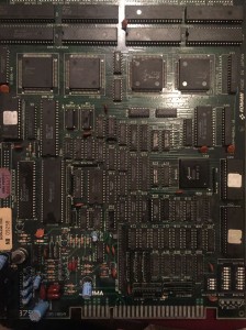
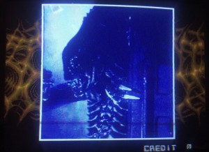
This Aliens had bad colours on certain things in the game, even though most others were fine.  Often the cause of this kind of fault is a bad graphics ROM but in this case the game includes a full self-test of the mask ROMs (and palette RAM) and no errors were reported.

IMG_7494

IMG_7650

IMG_7488

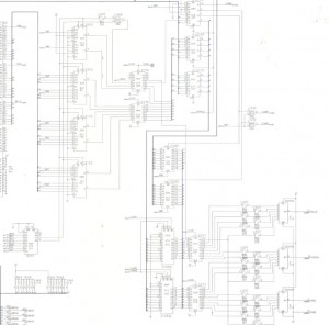
If it’s assumed the custom graphics chips are ok, then the first place to start with this kind of fault is in the palette mixing circuit.  In the schematic picture you can see all the relevant parts with the final RGB output in the lower left, and the graphics data coming in at the upper right to the group of LS153 chips.  The palette RAM is the two 2128 chips also in the lower right – as the name suggests this contains the RGB ‘pens’ the indexed graphics will use.  We can probably assume is is ok because the self-test said so.  The two LS273 latches to the right ‘cut up’ the signal per pixel – we know they are ok because if they weren’t all graphics would be bad, not just some.

Untitled-10

The two LS245 latches above the palette RAM are used when the CPU updates the palette – again, any error here would show in the self test.  The job of the 3 LS157 chips is to arbitrate between the graphics hardware accessing the palette RAM and the CPU accessing the palette RAM.  A fault here could cause bad graphics as it means the palette lookup could be wrong.  The LS245 chips hold the bytes going from the CPU into the RAM (or the bytes going back to CPU when reading it).

The group of 4 LS153 chips multiplex all the incoming graphics data and essentially handle layer priority – that’s what makes a sprite show over a background and under a foreground.  A fault here could also cause bad graphics – potentially sprites using the palette of the background, or background using the foreground palette and so on.

The two LS174 chips buffer the multiplexed output – any error here would likely show as all graphics being bad, not just some.

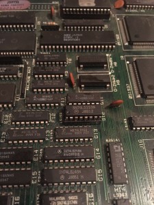
So, really the problem is likely be in just 1 of 7 chips, the LS153′s and the LS157′s, which can be examined with a logic probe (checking for stuck outputs or shorting outputs and seeing what happens on screen).  In this case the very first chip I tried (Fujitsu LS153 at G12) was bad.  It was replaced and all graphics perfect again.

IMG_7804 IMG_7803

IMG_7496

IMG_7811

IMG_7812

IMG_7818

IMG_7805

IMG_7814


By

SNK Ikari Warriors arcade pcb repair

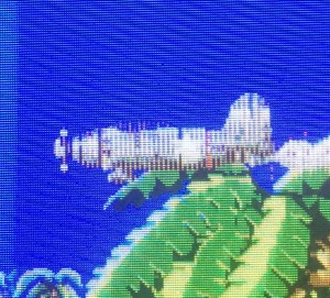
This Ikari Warriors was mostly fine, but had some specific bad graphics – the bullet on the title screen, the plane in the intro, grenades and power ups all displayed with a corrupt line effect.  Ikari has two sets of sprite generators – one for the players, enemies, tanks and one for the all the elements mentioned above, so it’s clear the fault was localised to the second sprite generator circuit only.  The middle board contains the 2 pairs of line buffer RAM, and shorting pins with a logic probe confirmed the top two chips were for the players, and the problem sprites were associated with the bottom two.  As it’s clear the graphics fault was on every second scanline, this was likely a problem in the line buffer setup (1 chip handles odd scanlines, 1 handles even.  If the glitch affected all lines then the problem is likely prior to the line buffer split).

IMG_7737 IMG_7732

After probing the chips feeding the RAM and finding no problems I assumed it was just a failed RAM chip.  So I removed both, but they tested fine off board and replacement RAM acted the same way on board – fault still present.  What’s more running the board with one of the RAMs removed showed the game logo also used the second sprite generator, but that wasn’t corrupt – so it seemed only some of the sprites were being corrupted, not all.  The sprite ROMs all tested good as well.  With no obvious dead chip this just got a lot harder to fix.

IMG_7743

Ikari does have a self-test mode – which reported no errors – and a debug sprite display mode – however it only displays sprites for that first sprite generator – the one with the players and enemies.  That is called ‘Front 2′ on the test and the schematics.  I modified the program to make it display ‘Front 1′ – the ROM is attached below.  This threw up an interesting fact – the corruption only happened on sprites using palettes 2, 6, 10, 13, 15 – so anything where bit 2 was set in the palette showed the error.  Very strange but I could verify this by always pulling bit 2 low on the LS245 chips that control the palette – bit 2 low graphics fine, bit 2 high – every other scanline showed an error.

IMG_7760


Referring to the schematics shows this is probably 1 of 4 chips.  The two LS374′s, or the two LS298′s.  The job of the LS374 is to pass data into the line buffer RAM pair as the line is built.  The job of the LS298 is to pass data out of the RAM and send it to the priority circuit on the top board.  The data going into the LS374′s must be good (because if it wasn’t the problem would show on every scanline, not just every second), and the circuit past the LS298′s must be good for the same reason.

schems

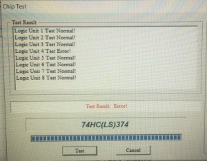
So, I desoldered the LS374′s and tested them – and a single bit error came up – on the pin that handles the palette bit 2!  Replaced and everything is fine, but what a really strange specific error.  Usually when chips fail all outputs go bad.

IMG_7771

IMG_7796 IMG_7786

Diagnostic ROM – up03_l4.front_1_diagnostic


By

Taito Chase HQ arcade pcb repair #3

I was sent this untested pcb and when I wired it up found there was no video output on RGB – very strange as sync was present, so this caused me to check and re-check my wiring a few times.  When examining the pcb closer it was clear the TC0070RGB custom had been removed, presumably to fix a different game.  I had a spare one so I soldered it in and everything was back to working.

IMG_7530

See here www.jammarcade.net/taito-tc0070rgb-reproduction/ if you need this part.


By

Nintendo Mario Bros arcade pcb repair #4 / Ghetto Fluke

Another Mario Bros – again booting to a screen of garbage tiles. I attached the video (bottom) board to a known good CPU (top) board and apart from a glitch fixed by reseating the ROMs the video output was fine. So any problems were on the top board.

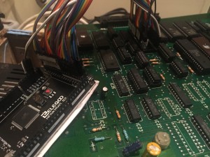
There were a bunch of obviously corroded Fujitsu IC’s that a logic probe showed had dead outputs, but even when replaced the game didn’t boot. Piggy-backing known good RAM chips didn’t help either. Rather than start shotgun replacing parts I decided to try out an idea I’ve had a for couple of years – use an Arduino or Raspberry Pi style device to replace the CPU and probe the board for faults that way. The idea is that the Arduino device will connect to the data and address bus as well as the read/write pins so that you can manually run tests that may show up faults. For example, reading ROMs, testing main RAM, writing to graphics RAM or sound latches.

My idea isn’t unique – I know Paul Swan has made a similar device – http://www.paulswan.me/arcade/ArduinoMegaICT.htm as well as a chap called Artemio who has helpfully placed code for a Z80 setup on Github – https://github.com/ArtemioUrbina/GhettoFluke9010A

The Mega Arduino was wired up – GND, 16 address lines, 8 data, various read/write/bus ready control lines, etc, plus 12V from game PSU powering the Arduino itself. I added a test to read each of the ROM chips and print the CRC’s. After some debugging of my setup all the ROM chips came back with the same CRC’s as MAME – great news, so for sure the CPU can read the program properly. I wrote a test that writes to and reads back the two RAM chips – this returned garbage values. The useful thing about this setup is that I can ‘pause’ the current state at any time and examine chips with a logic probe. So with all activity frozen it was easy to see the chip select line on the RAM was not being enabled when it should be. With the schematics this was traced back to a LS138 chip that had dead outputs.

With that replaced I wrote an incrementing numeric sequence to RAM – but the sequence read back with duplicated sections – so the RAM address decoder had surely failed internally and bytes written were going to the ‘wrong’ place. (As an aside this explains why piggybacking a known good RAM didn’t work – the RAM outputs were working fine – just address conflicts internally).

With the RAM replaced the game booted and worked fine albeit with most sounds missing!

I used the Arduino again to trigger all sound ports one by one and checked with the logic probe and schematics that all the right pins pulsed at the right time on the audio CPU. In fact the audio CPU itself was dead as confirmed when a known good one was placed on the board. The audio program eprom was also bad (returned 0xff for every byte), so a replacement was burned.

Another Mario saved.

[It seems the pictures for this post were lost - here is a picture of the Arduino attached to a Bubble Bobble bootleg for an upcoming repair].

IMG_7411