BryanMcPhail.com

Professional software development, amateur BMW tinkering, old arcade game stuff

By

Irem Air Duel arcade pcb repair

An original Irem Air Duel, though when I disassembled it I found an R-Type sticker on the middle board as well.  Air Duel was actually released as two different pcbs – the ‘M82′ board as well as the ‘M72′ like R-Type.  Although R-Type is considered a great title now, I’m not sure it sold very well when first released, and I suspect Irem were using up unsold R-Type boards when they released the M72 version of Air Duel.

IMG_8997 IMG_8996

This board came up some garbage when first powered on, then went to a solid black screen.  The fact the board did something proved the CPU was running.  I knew from the MAME driver this board has software control over blanking the screen so I decided to start there.  On the schematics this is the CBLK signal which is combined at the LS32 OR gate at IC63.  Logic probe showed the output of this was always low no matter what the inputs were.  So bad LS32?

IMG_9001

Well, bit of a weird one – the output of the LS32 goes to CN2 (the ribbon cable to the video board) and that pin had continuity to ground with the cable connected.  So bad video board?  Nope, bad cable – a ‘PC’ style IDE cable was used rather than the Irem original and the pins are actually inverted (so the top row went to the bottom row) and this just happened to ground out that LS32.  Of course a whole lot of other pins were connected in the wrong way too – so quite lucky it displayed anything.  Original Irem cables were taken from a parts board and the game worked fine.

IMG_9009 IMG_9002 IMG_9007


By

Atari Badlands arcade pcb repair

Two broken boards picked up on KLOV..  I knew they had some missing chips but I only had a quick glance and thought it was just the 68000 and 6502 CPUs plus some eproms.  On closer inspection though I found the custom Atari ‘LETA’ chip was missing.  That’s also used on more valuable titles like APB and 720 so most likely these boards had been parts scavenged at some point.  The LETA chip handles encoding of the steering wheel inputs to the game – but the game should still run without it, so let’s see what was up..

IMG_8484

With the CPUs and eproms replaced there was no video output and no CPU activity – in fact the CPU reset signal didn’t seem to be working either.  According to the schematics the reset depends on v-blank, which comes from the ‘SOS-2′ custom chip.  This chip only has a couple of inputs – the main video clock (14MHz) and an inverted 256H (scanline) signal.  The clock was good but the scanline timer stuck.  The non-inverted signal actually comes from the SOS-2 as well in a feedback circuit – so bad SOS-2?

IMG_8494

A replacement made no difference, but the trick is check what the signals are doing with the chip removed from the board.  The outputs should all be floating with nothing driving them (1H to 256H and 1V to 128V) – but 256H was still stuck low.  So actually the PAL @ 26R that takes 256H as an input had failed in such a way that the input was stuck low.  Replacing this PAL unstuck the timing, and there was now garbage video displayed – progress!

IMG_8490

With one bad PAL found I checked the others – and 3 of them became extremely hot extremely quickly.  These 3 were replaced and the game sprung into life!

IMG_8504

IMG_8499

Still no inputs of course but JROK did design a replacement LETA chip which you can read about here http://www.jrok.com/project/leta/index.htm

I probably won’t go that route – adapting the game to use a regular JAMMA joystick sounds more interesting… for a future post.

Board 2

Unfortunately this had bad main RAM – pretty clear why as it was plugged into the board backwards and absolutely fried.  The RAM type (MB87316) is pretty rare – I think only used on Klax and a couple of other Atari games from this era.  I’ll shelf this board until some RAM turns up.

IMG_8510


By

Konami Hyper Olympic bootleg arcade pcb repair

This board worked but had a strange magenta outline around the characters.  This was a very time consuming repair for what seemed a little fault, it didn’t help I started down the completely wrong path..

IMG_8079

IMG_8317

What wasn’t the problem

The eproms and color prom all tested good – so it wasn’t a simple case of corrupt data.  I’ve talked in many repair logs about pairs of sprite line buffers, which are present on this board as many others.  Because the magenta outline was present on all scanlines, this meant the problem had to be after the eproms (where the sprite data is sourced) but before the split into the two line buffers OR after the two line buffers are recombined before reaching the color prom.  So this cuts the potential problem chips right down – the eprom data goes to a bunch of 4 LS194 shift registers, which feed into the two sprite RAMs.  The data leaving the RAM travels to a LS273 then a LS157 which recombines into a single data stream (which goes to the LS258 which acts as the priority selecter by picking between either a sprite pixel going to the color prom or a tilemap pixel).

However, every single chip tested good, so this theory ended up being a complete waste of time.

What was the problem

The clue came when I forced the color prom to display only tilemap colors or only sprite colors (you can do this by forcing the top address line of the colour PROM either high or low – as per OBJOUTD at pin 14 on the schematics).  With the sprite palette forced on the sprites were 100% correct – after checking the palette in MAME I finally understood the fault – the ‘first’ pixel of the sprite was using the tilemap palette, as the magenta only existed in the tilemap palette and was being used instead of the dark brown expected by the sprite.

IMG_8327

IMG_8336

So why could that be…  In the schematics you can see OBJOUTD controls the prom switching between tilemaps and sprites, but the OBJOUT signal controls the data switching.  A LS174 makes the OBJOUTD and you can see it’s generated 1 CLK later on from OBJOUT.  Why I have no idea..  I didn’t find any problem there so I just patched OBJOUT to drive the prom directly – and this made the magenta outline appear on the right side, rather than left.  So instead of the prom palette being a pixel behind it was now a pixel ahead.  So it was as if the switch happened ‘half a clock’ out of time which is pretty weird.

IMG_8334.

I examined what drove the CLK1 and /CLK1 signals which was an LS368.  On the original Konami board a custom chip drives the LS368.  However, on the bootleg was a weird hack involving two capacitors on the clock input line – one was damaged and removing it made the graphics perfect!  Not altogether uncommon to see hacks like this on a bootleg (a capacitor delaying a clock, in this case by ‘half’ or inverted phase) but not easy to find.

IMG_8330

IMG_8340


By

Konami Track And Field arcade pcb repair #3

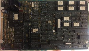
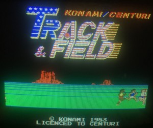
Board booted to a screen full of zeroes which is an indication the CPU is running the start of the program at least (if not the screen would be full of random garbage rather than a consistent pattern).  Checking the eproms on PC found a couple were bad (inconsistent reads) but the main problem was the RAM chip next to the eproms was dead.  The part number is scratched out but it’s just a regular 6116 style RAM.

IMG_8068

IMG_8069

With that replaced the board booted to the title screen – but with obviously bad sprites in both the tile index and the Y position on screen.  The game also reset before entering gameplay, so definitely still a CPU/RAM related problem.  There are schematics available for this game, which show the custom chips used for sprite processing.  This board however, didn’t use any custom chips but instead had little daughterboards with regular TTL chips.  This is actually quite common in all of the Centuri licensed boards I’ve seen – probably there was a manufacturing shortage of the custom chips and the daughterboards were put in to meet demand.  I set about removing the daughterboards for test (the board should run without crashing, just no sprites, with them removed) and the board ran fine.  I then ran the board with the daughterboard sitting in the desoldered holes – and it ran 100% fine with working sprites!  It kept on working with the board soldered back on and a long soak test.  Very strange, I can only guess there was some kind of solder bridge short on the board somewhere, and the act of applying heat to remove the daughterboard cleaned it up.

IMG_8072

IMG_8173

Finally bad inputs were fixed by replacing a smashed resistor pack with one from a parts board.

IMG_8073


By

Midway Terminator 2 arcade pcb repair

Game was initially dead with video or sound output.  The TMS34010 CPU is the fore-runner of the CPU used in my earlier Battletoads repair and shares most traits with it including control pins that can halt the CPU for external memory access.  The logic probe showed a very similar problem to Battletoads initially – the CPU was resetting properly, getting a clock signal, but had no activity on the data/address bus.  Something was holding the LRDY (local ready) pin low so the CPU appeared to be in a wait state for something external.  That something was traced to the Intel security chip which is not replaceable if it has failed.  Luckily it hadn’t failed – the problem was that chip was not getting a clock signal so it was also stuck causing a deadlock.  I checked with the schematics and found the clock signal for the Intel chip came from…  the TMS34010 CPU.  This CPU actually provides clock outputs as well as having a clock input and it seemed this part of the CPU die had failed – a replacement CPU taken from a Mortal Kombat 2 board got the board to boot to the test menu, albeit unstable and crashing after a few seconds.  (The MK2 pcb failed to boot with the T2 CPU proving the CPU itself was bad).

IMG_8355

Finding the instability took much longer…  there was a previous repair to the board with 4 RAM chips replaced.  These all share a common data and address bus but a continuity check showed 2 chips had a couple of unconnected data lines – the soldered pins were not making good contact with the traces/thru-holes (specifically traces on the top side of the board rather than solder side).  With the solder reflowed the board was 100% again.

IMG_8353

IMG_8351 IMG_8359


By

Konami Simpsons arcade pcb repair

Board would not boot most of the time – when it did the check screen showed an EEPROM error as well as a ROM error.  The background of the check screen was also red when it should be black.

The EEPROMs on Konami games are known for failing, but a check with a logic probe and multimeter here showed that 5 of the 8 pins weren’t even connected – trace damage where the chip met the pcb.  With that repaired it made absolutely no difference to the boot failures or bad check screen.  In fact the logic probe showed the software wasn’t even trying to read the EEPROM as the chip select or clock pins never pulsed.  After checking the chips involved with reading the EEPROM data (shown in the schematics as EEPDI, EEPCLK, EEPCS) were fine I suspected the PAL chips used to form the memory map may have failed in a subtle way and were responsible for both the EEPROM error as well as the ROM one.  This was a fault I had encountered in the previous Konami Vendetta repair – the PAL worked enough to boot the game to the check screen but failed in some kind of edge case that would give bad output over certain memory regions.  Simpsons has two PALs like this – marked as 55394 and 55395.  55395 is the one that directly enables the EEPROM, but replacing this made no difference.  Replacing 55394 though finally enabled the game to boot properly with no errors – so the fault was most likely that it was activating regions at the wrong time.

IMG_8083

IMG_8081

The game still had a fault with the red channel stuck on, as well as not booting most of the time.  As I knew the palette RAM was ok (because of the game self test) I started with the custom 052535 DAC IC.  Replacing this made no change, I should have paid more attention to the schematics as there was also a LS273 chip in between the palette RAM and the DAC and this had simply failed with outputs stuck high.

IMG_8090

IMG_8091

IMG_8087

Inconsistent boot faults can be much harder to track down though – in this case I got a clue it was a physical problem when I found it would boot if I flexed the PCB a certain way.  Reflowing the solder on the surface mount custom ICs made no difference but removing all the ROMs and cleaning the ROM sockets did – one program ROM socket had a strangely dirty pin even though all the others were fine.  Game now booted and ran 100% of the time.

IMG_8274