BryanMcPhail.com

Professional software development, amateur BMW tinkering, old arcade game stuff

By

Sega Enduro Racer arcade pcb repair

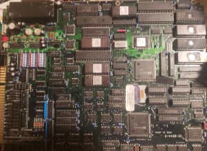
Mainboard 1

This board had the original 35 year old battery backed suicide CPU still installed.  When the battery dies the encryption key is lost and the CPU will execute garbage.  Replacing this with decrypted ROMs and a plain 68000 was the first thing to do, and the board booted up with a graphics fault.

_e1

The SEGA letters were visible, just in the wrong place which suggested an addressing problem.  I probed in the area around the tilemap RAM (IC113 in schematics) and found a LS367 @ IC128 with dead outputs.  Replacing this fixed the tilemap.

_e2

Rom Board

The game was now mostly correct but some sprites were wrong/missing, the most obvious thing being most of the Sega logo on the title screen.  The ROM board is packed full of ROMs but it’s really just 4 sets of 8 – each set supplies 8 bits at a time to the 32 bit graphics processor.  I used MAME to disable each set one at a time and I found removing the 3rd ROM replicated the fault.  The ROM tested good on the board but a probe showed one of the address lines was floating – presumably some kind of corrosion under the socket.  The address lines are all shared between all the ROMs so this was easy to patch.

_e3


Sound Board

Just to complete the set of problems, the sound board had a bunch of missing and broken capacitors needing replaced – one in particular shorting +5V and GND.


Mainboard 2

This mainboard also still had the original 35 year old battery CPU and it booted up!  It only lasted a few days though and needed replacement as per the other one.

_e23


e9

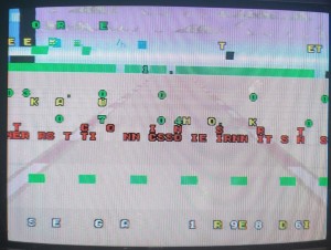
This board had a weirder graphics fault on the video board – text appeared underneath sprites, sprites were wrong colour and seemed transparent in places.  I found the video mixer part of the circuit in the schematics and found priority is calculated by a CK2605 PAL device.  All outputs were dead, and this was confirmed by using the PAL from the working board.  A replacement was ordered from RetroClinic to fix this board fully.
_e11

_e6 e7


By

Konami G.I. Joe arcade pcb repair

Very clean board but booted to corrupt screen with continual watchdog resets.  Like most Konami games of this era the watchdog can be disabled by bridging the jumper near the edge connector.  With the resets taken care of the 68000 CPU was stuck and not running – however it wasn’t stuck in HALT mode, instead it was waiting for a DTACK signal.  When the 68000 writes to an address it waits for the receiver to signal it has received the data via DTACK.  (Not all games do this, some just tie DTACK low and assume whatever was written got there).

There are no schematics for this game so I had to spent some time tracing out the board.  DTACK is driven from the LS00 NAND gate at 4g.  The LS00 is driven from the LS74 at 2g and the LS30 at 7g.  A logic probe on these chips revealed a dead output on one side of the LS74.  With a replacement soldered in the game was perfect.

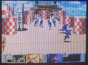
_gi1 _gi2 _gi3


By

Tecmo Rygar arcade pcb repair

Game played but had no sound.  The audio amp (M51516L) was getting 12V ok, but produced absolutely no hum or hiss which is a good sign the amp itself has failed.  Before replacing I tried the usual trick of attaching power speakers to the preamp outputs but this didn’t give any sound either.  The audio CPU, ROM and RAM all tested good so I moved onto the YM3526 sound chip.  The IRQ pin was pulsing which is a good sign it’s working as the CPU must program the IRQ timer for this to happen.  However, a scope on the digital audio output stream showed it wasn’t trying to play any sound.

My next theory was the main CPU wasn’t telling the audio CPU to play anything – most games of this era use an 8 bit latch to pass sound commands.  The main CPU writes the audio command into the latch then signals an interrupt on the audio CPU to signal command data is ready.  A logic probe on the audio CPU NMI line showed it pulsing whenever a sound should play (such as coin insertion) so I took some guesses at what chip the latch was and found a nearby Fujitsu LS374 where the clock also pulsed on coin insertion (main CPU writing the command) as well as output enable (audio CPU reading the command).   Sound worked with a known good LS374 piggybacked over the top, so the Fujitsu chip had failed and was likely passing 0xff (all 8 bits high) for all audio commands.

After the LS374 and M51516L were replaced everything worked again.

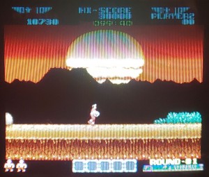
_ry

By

Data East Desert Assault arcade pcb repair

Game booted to a solid green screen or sometimes would not boot at all.

The first fix was simple – the ROM sockets and ROM legs were very dirty and oxidised.  1200 grit sandpaper on the ROM legs and Deoxit in the sockets cleaned things up enough that it would boot consistently.

The next fault was a real headscratcher – in the attract mode the screen wouldn’t scroll – the characters just ran to the right hand side and got stuck.  Starting a game had a similar fault.  This was clearly a program logic error – however the ROMs had tested good, and it was likely the RAM was good as well (piggybacking known good RAM made no difference).

_d3

The fault didn’t become clear until I started swapping the top and bottom boards with a few other working Desert Assaults.  Desert Assault is a dual CPU game, with a 68000 on each board and in this case the top board had a different revision of the program than the bottom board.  Someone must have tried to repair the board in the past with fresh ROMs but only replaced the top set (bottom set was still original).  Reburning the top ROMs fixed the fault.

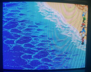
_d2 _d1

By

Atari Gauntlet 2 arcade pcb repair

Game worked but had artifacts on certain sprites in certain locations – usually vertical lines down the screen on every other scanline.

_g2

My first guess was failing object (sprite) RAM, which are the 4 RAM chips in the corner of the board.  All 4 were socketed and replaced and at first I thought the problem was fixed.  However this was more a case of the different brand of RAM acting a bit differently – the vertical lines were mostly fixed but certain sprites still had ‘sparkly’ artifacts.    After checks on the IC’s that drive the data and address lines I found a physical problem – a hairline crack on a pullup resistor pack.  Despite the crack it tested fine (470ohms on each pin) but the sister pack seemed to have an internal failure – 4 of the 8 pins showed 960ohms.  Both resistor packs were replaced and the sprites were properly fixed.

_g1

The purpose of the pullup resistor packs is provide an all high data signal to ‘erase’ pixels in the line buffer when no sprite data is active.  With the higher resistance the voltage on the data pins was lower and likely in the intermediate range between low and high.  So the sparkles were certain pixels randomly being regarded as low instead of high.