BryanMcPhail.com

Professional software development, amateur BMW tinkering, old arcade game stuff

By

Technos Renegade arcade PCB repair

Renegade is a JAMMA pcb and the predecessor to Double Dragon.  Initially it seemed the vertical sync was broken on this board – the image rolled vertically very fast.  I traced the sync line from the JAMMA connector back on the top board and found it goes to the bottom (video) board.  After cleaning up a lot of dirt and dust, a massive gouge in the bottom board became clear!  Must have been a fairly heavy impact as you can see two TTL pins are sheared clean off.

IMG_0532 IMG_0533 IMG_0528

Bridged the broken traces with wire and sync was restored but the image was cut into three pieces.

IMG_0537 IMG_0536

Re-checked the repair with a logic probe and found no activity on one of the repaired traces.  There was actually a through-hole to the other side of the pcb in the damaged area that need soldered back on the trace.  Then everything worked 100%.

IMG_0546 IMG_0543 IMG_0542


By

Data East Hoops 95 pcb non-repair

This is the Data East MLC package – which is a two layer pcb inside a protective plastic box.  Unfortunately this one seems 100% dead – no video or sound output at all.  Components are actually surface mounted to all 4 surfaces on the two layers – the main CPU (an encrypted ARM) actually sits on an inside surface so it’s hard to diagnose directly.

Using a logic probe with the game powered on shows that the data and address lines on the program EPROMS are pulsing – so the CPU is definitely trying to do something.  All the graphics hardware (ROMs, custom chip) probes as completely dead – that doesn’t prove for sure that it is dead – it may be the CPU is actually failing for some reason and not instructing the graphics customs to start up.  My immediate theory would be one of the main RAM chips for the CPU has failed – these are 4 Winbond chips on the main board.  The ARM is a 32 bit chip and these 8 bit chips run in parallel so a failure in any one of them would cause the CPU program to immediately fail.

Hoops isn’t that great a game, so I’ve no plans to probe further – this can wait until I find another MLC game and swap the top & bottom boards and see what happens.

IMG_0616 IMG_0618 IMG_0617IMG_0619

By

Namco Sky Kid pcb

Bought as a non-worker for parts – actually it works 100%!  The non-obvious catch is that who-ever made the JAMMA adaptor wired it upside down!?  The tell-tale sign is the ‘double’ +5V and GND traces are on the right instead of the left.

IMG_0613 IMG_0608 IMG_0607 IMG_0605 IMG_0604

By

Super Chase / Hantarex Polo

A reasonably rare/overlooked game from Taito in 1992. This was completely dead when I got it – no lights, sounds, picture. The power supply was the first problem as it wasn’t able to supply +5V to the pcb. In fact I had to try 3 (used) power supplies until I found one that could give a consistent +5. This pcb draws a lot more current than a lot of older titles (probably as it uses a 68020 CPU and two sub 68000 cpus, plus a lot of graphics and sound ic’s that were cutting edge at the time) so some power supplies can’t keep up and voltage drops.

IMG_0234 IMG_0251

This made two LED’s on the light driver board illuminate, but still nothing else. The sound board is quite unusual in it expects +13V as well as +5V and +12V. Without the +13V line connected the sound amps don’t work at all – however putting 12V there made them work well enough that I could hear game sounds – so pcb confirmed as running! [I should mention that Super Chase isn't jamma - so I couldn't just test it in another cabinet].

The monitor remained completely dead – it’s a Hantarex Polo 25″ standard resolution. No signs on physical problems (cold solder joints, blown fuses, burnt areas, broken components). I hate working on high voltage stuff, so rather than debug anything I decided just to shotgun replace the flyback, all capacitors, and the HOT (horizontal output transistor). On a 23 year old monitor it’s a good bet the capacitors need replacing, and the flyback may have failed. Internet repair logs on this monitor suggest bad flybacks can kill the HOT, so as it’s only $5 may as well replace it too.

IMG_0250 IMG_0249

And it worked! It’s quite unusual for a cap kit to bring a dead monitor back to life, but the Polo has a built in power supply (no isolation transformer needed) so bad caps there were probably the primary reason for not turning on. Monitor looks good as new now.

A cool thing about Super Chase is the flashing lights – these are just 40W incandescent bulbs, but both were blown – replaced them, and replaced a blown fuse on the driver board and all was good there. The driver board is quite a simple thing – it takes two 5V lines from the game pcb as input, a 110V mains source, and outputs two 110V lines to the bulbs. You can see the board is designed for 4 lights, but only 2 channels are populated.

IMG_0264 IMG_0262

(Main marquee light still not fixed in picture below)

IMG_0268IMG_0278 IMG_0275


By

Pacland PCB repair

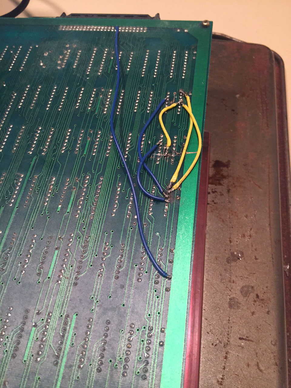
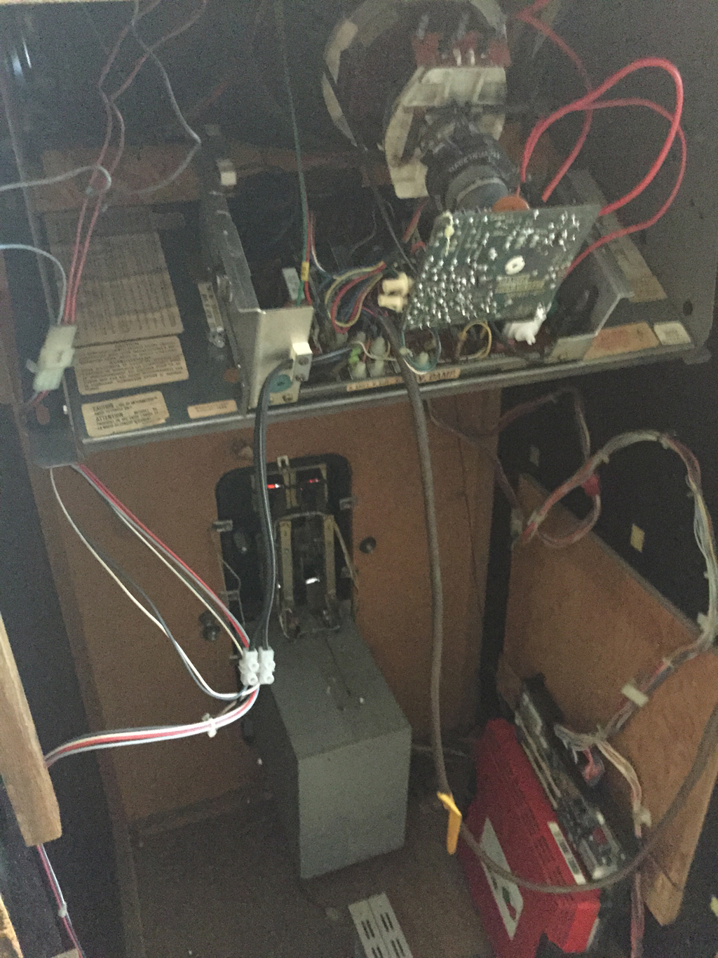
After making a custom loom for this untested pcb, I found it booted to garbage. Booting to garbage is at least better than not booting at all though as it shows the video output section is at least running.  After checking the voltages at the chips were 5V (or slightly higher) and that the program eproms I examined other socketed chips and found the custom chip 34 had badly corroded pins when removed from the socket, and a few of the legs snapped completely.


Repair 1 – clean up the corrosion and mount the chip in a new socket and solder through from the broken pins to the socket top. Not the prettiest fix but it works.


Unfortunately, this didn’t change much with regards the corruption. So I put a logic probe on the CPU and found the clock pins (Q & E) and the address and data bus pins had activity on them. However, the read/write pin seemed stuck high – this means the CPU could only be reading from RAM, never writing to it and a CPU that can’t write data certainly can’t run properly. The CPU also got very hot very quickly.

Theory 1 – CPU has failed internally, and R/W has stuck high.
Theory 2 – the chip the R/W pin connects to has failed and forced the R/W line high regardless of what the CPU tries to do.

The CPU is in a socket so that’s the easiest thing to try first – however I didn’t own others of this type to swap in (HD6309, slightly different from regular M6809) so had to wait a week to order some from Ebay.

And.. didn’t help, no change. The R/w pin connects to an LS368 chip at location 5A and suspiciously it has corroded pins, even though all the chips around it are perfect. So remove and replace that.

And.. still corruption, though it’s different and it seems the CPU is definitely doing ‘something’ as the corruption cycles a few times before stopping. In retrospect I think the stuck R/w pin theory was a bit flawed – if it was truly stuck then the corruption would probably be random each time, and this was consistent. Instead more likely the CPU started to run the program then just parked itself in an infinite read loop when it detected a failure.  The LS368 was probably bad in some other way though.

So Pacland in MAME shows that on boot the game should print 0 0 0 on screen to show all self-tests passed.  The curious thing about the new corruption is you could clearly see the screen clear a few times then a couple of zeros appeared, just not where you would expect them to be.

So new theory – RAM is bad – as when the CPU tries to write the zero character it gets reflected in a bunch of other locations (so the internal address decoding has failed).  So, desolder and test the 7 6116 RAM chips on the top right of the board.  The top 4 is the RAM for the tile maps, the bottom 3 is for the sprites and CPU workram.

Unfortunately, all the RAM tested good.  So..  time to examine the schematics to see what is in-between the RAM and the CPU.  I desoldered the IC’s at 10B, 9E, 9D, 10N, 9F – these control the enable lines to the RAM.  All tested good so no progress.

Usually in arcade schematics you read from left to right – inputs on the left, and outputs on the right.  There’s an exception in Pacland though, as the tile map ram chips can be addressed by the main CPU, or by the graphics hardware through a custom chip.  So the address bus on the right of the RAM in the schematics is actually an input, and it comes from a pair of LS365 chips.  These chips seems relatively rare on arcade pcbs, and my tester doesn’t support them.  Their use seems to be in allowing both the CPU and graphics hardware access to the RAM chips.  This is driven by the 2H signal – from the name I assume it toggles twice for every horizontal pixel – so for every pixel on the screen both the CPU and graphics get RAM access.

Switched these chips out for new – and instantly no more corruption!  The 0 0 2 self test signals bad RAM, but this was expected as I hadn’t replaced the sprite ram at this point.

In game however, corruption remained on the backgrounds, but at least sprites and logic were working 100%!  Time to look at the video part of the schematics which I’d mostly ignored until now.  Custom chip 36 makes the tile maps.  It has access to the tile map ram of course, two eproms with graphics data, and two color proms.  We know the tile map RAM itself is good, so time to test the LS174 and LS86 chips that drive addressing to the graphics eprom.  Unfortunately all tested good, so the problem wasn’t there.

Tracing back further shows a LS365 and LS366 involved in addressing the tile map ram from the graphics side (NOT used by the CPU side access).  Really I should have tested them first as having already found a bad LS365 there’s a good chance another from the same batch would have failed in the same way.  Replaced these and everything was good!


Time taken : > 10 hours over 3 weeks (lots of waiting for parts to arrive)

By

Rastan PCB repair

Ok, calling this is a ‘repair’ is probably a misrepresentation as it was so easy. I bought this pcb from a junk pile and it arrived a bit dusty but not physically damaged in any way. It was missing all eproms (68K program, Z80 audio program, audio samples eprom) and the socketed PAL at IC58 (PAL16L8). The schematics show that IC58 generates monitor sync so it definitely wasn’t going to show anything without that..

Burned all eproms from the MAME set, and the PAL16L8 onto a GAL with thanks to the PLD images at http://www.jammarcade.net/pal-dumps/

And it worked! Well, almost – no sound and wouldn’t accept any coins. It seems this is due to the connector marked H on the board. I’d assumed this was a stereo sound output, but it seems 12V is required here in order to power the sound amp and coin IO. 12V from the jamma connector already runs here – so you have to jumper pins 1 & 2 together and 3 & 4 together to enable sound & coins. With this done the game worked fine.

Mystery 1 – why does connector H even exist, when 12V is already at the jamma connector!?
Mystery 2 – why did an operator strip a (presumably) working board just for some cheap eproms and a PAL? I guess something else more important at the time needed the parts.

By

Donkey Kong 3 pcb repair

Well, not really a repair as it was so simple.  Game booted consistently to the same garbage.  The usually suggests the CPU is doing something (as the garbage would be random each time if it wasn’t) but goes wrong because of RAM or other IC’s.  However, replacing the socketed Z80 CPU fixed it!  Easy fixes are always good.

IMG_9428 IMG_9785 IMG_9787

I must admit I made a mistake when wiring the pcb at one point (DK3 style edge connector to old style DK block connectors) and ran monitor blue to sync and vice versa.  The monitor actually managed to sync to the blue output – and then you can see the sync represented on blue on screen.  The long blue line is really the vertical blank sync, and the short blue lines are the horizontal sync pulses – they are just all out of place of course.  So if your game looks like this – check wiring!

IMG_9425


By

Wells Gardner K4900 monitor fix

This JAMMA cabinet had gone pop almost two years ago, time to diagnose why. On applying power the primary fault was quickly identified – high voltage fireworks were literally shooting out the top of the flyback! You can see the burn marks on the picture, but there is probably a hairline crack as well.

So, remove old flyback, install new one… and it worked! Great to find the fault hadn’t taken out anything else on the board. Usually this would be a good time to install a cap kit, but it seems the previous owner must have done this at some point, as all the caps looked new. (Disclaimer, do not attempt to remove or even touch the flyback or tube if you don’t understand how to safely discharge a CRT. Very high voltages can be present even with power off).

Apart from some screen burn in, picture quality is great for a 33 year old monitor!