BryanMcPhail.com

Professional software development, amateur BMW tinkering, old arcade game stuff

By

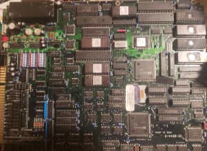
Atari Gauntlet 2 arcade pcb repair

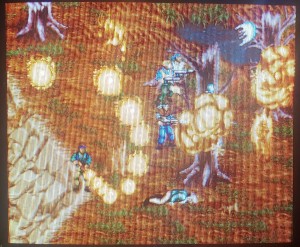
Board showed missing graphics on the title screen and blocks in game were often wrong.

_g21

After some diagnosis it became clear the scroll position on the tilemap was wrong – rather than actually anything wrong with the tilemap itself.  The missing title screen graphics were instead horizontally scrolled off screen by 256 pixels.

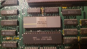
The scroll position is controlled by the 137419-104 custom chip and this seems to have failed with the 256H line stuck high.  Fortunately this chip is also on a few other Atari games, including Pit Fighter, so I pulled a chip from a corroded parts board to fix the Gauntlet.

_g23 _g25

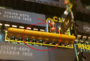
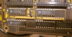
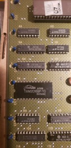
The board had another fault I recognised immediately from another repair – sprites with ‘sparkly’ vertical lines down the screen.  This is a failure of the resistor packs used to pull the sprite data lines high when erasing a scanline.  These packs are at the corner of the board, so any flexing of the board can lead to hairline fractures.  470ohm resistors can be used as a replacement.

_g24 _g26


By

Arcade repair posts

I’ve still been repairing but have had little time over the past year to write up any posts.  I’ll still try to document the more interesting ones though.


By

Email

It seems email to this site went down over the past few months and I didn’t notice.  If you emailed me and I didn’t reply please assume I never received it!


By

Sega Enduro Racer arcade pcb repair

Mainboard 1

This board had the original 35 year old battery backed suicide CPU still installed.  When the battery dies the encryption key is lost and the CPU will execute garbage.  Replacing this with decrypted ROMs and a plain 68000 was the first thing to do, and the board booted up with a graphics fault.

_e1

The SEGA letters were visible, just in the wrong place which suggested an addressing problem.  I probed in the area around the tilemap RAM (IC113 in schematics) and found a LS367 @ IC128 with dead outputs.  Replacing this fixed the tilemap.

_e2

Rom Board

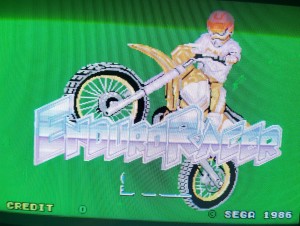
The game was now mostly correct but some sprites were wrong/missing, the most obvious thing being most of the Sega logo on the title screen.  The ROM board is packed full of ROMs but it’s really just 4 sets of 8 – each set supplies 8 bits at a time to the 32 bit graphics processor.  I used MAME to disable each set one at a time and I found removing the 3rd ROM replicated the fault.  The ROM tested good on the board but a probe showed one of the address lines was floating – presumably some kind of corrosion under the socket.  The address lines are all shared between all the ROMs so this was easy to patch.

_e3


Sound Board

Just to complete the set of problems, the sound board had a bunch of missing and broken capacitors needing replaced – one in particular shorting +5V and GND.


Mainboard 2

This mainboard also still had the original 35 year old battery CPU and it booted up!  It only lasted a few days though and needed replacement as per the other one.

_e23


e9

This board had a weirder graphics fault on the video board – text appeared underneath sprites, sprites were wrong colour and seemed transparent in places.  I found the video mixer part of the circuit in the schematics and found priority is calculated by a CK2605 PAL device.  All outputs were dead, and this was confirmed by using the PAL from the working board.  A replacement was ordered from RetroClinic to fix this board fully.

_e11

_e6 e7


By

Konami G.I. Joe arcade pcb repair

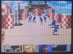
Very clean board but booted to corrupt screen with continual watchdog resets.  Like most Konami games of this era the watchdog can be disabled by bridging the jumper near the edge connector.  With the resets taken care of the 68000 CPU was stuck and not running – however it wasn’t stuck in HALT mode, instead it was waiting for a DTACK signal.  When the 68000 writes to an address it waits for the receiver to signal it has received the data via DTACK.  (Not all games do this, some just tie DTACK low and assume whatever was written got there).

There are no schematics for this game so I had to spent some time tracing out the board.  DTACK is driven from the LS00 NAND gate at 4g.  The LS00 is driven from the LS74 at 2g and the LS30 at 7g.  A logic probe on these chips revealed a dead output on one side of the LS74.  With a replacement soldered in the game was perfect.

_gi1 _gi2 _gi3


By

Tecmo Rygar arcade pcb repair

Game played but had no sound.  The audio amp (M51516L) was getting 12V ok, but produced absolutely no hum or hiss which is a good sign the amp itself has failed.  Before replacing I tried the usual trick of attaching power speakers to the preamp outputs but this didn’t give any sound either.  The audio CPU, ROM and RAM all tested good so I moved onto the YM3526 sound chip.  The IRQ pin was pulsing which is a good sign it’s working as the CPU must program the IRQ timer for this to happen.  However, a scope on the digital audio output stream showed it wasn’t trying to play any sound.

My next theory was the main CPU wasn’t telling the audio CPU to play anything – most games of this era use an 8 bit latch to pass sound commands.  The main CPU writes the audio command into the latch then signals an interrupt on the audio CPU to signal command data is ready.  A logic probe on the audio CPU NMI line showed it pulsing whenever a sound should play (such as coin insertion) so I took some guesses at what chip the latch was and found a nearby Fujitsu LS374 where the clock also pulsed on coin insertion (main CPU writing the command) as well as output enable (audio CPU reading the command).   Sound worked with a known good LS374 piggybacked over the top, so the Fujitsu chip had failed and was likely passing 0xff (all 8 bits high) for all audio commands.

After the LS374 and M51516L were replaced everything worked again.

_ry

By

Data East Desert Assault arcade pcb repair

Game booted to a solid green screen or sometimes would not boot at all.

The first fix was simple – the ROM sockets and ROM legs were very dirty and oxidised.  1200 grit sandpaper on the ROM legs and Deoxit in the sockets cleaned things up enough that it would boot consistently.

The next fault was a real headscratcher – in the attract mode the screen wouldn’t scroll – the characters just ran to the right hand side and got stuck.  Starting a game had a similar fault.  This was clearly a program logic error – however the ROMs had tested good, and it was likely the RAM was good as well (piggybacking known good RAM made no difference).

_d3

The fault didn’t become clear until I started swapping the top and bottom boards with a few other working Desert Assaults.  Desert Assault is a dual CPU game, with a 68000 on each board and in this case the top board had a different revision of the program than the bottom board.  Someone must have tried to repair the board in the past with fresh ROMs but only replaced the top set (bottom set was still original).  Reburning the top ROMs fixed the fault.

_d2 _d1

By

Atari Gauntlet 2 arcade pcb repair

Game worked but had artifacts on certain sprites in certain locations – usually vertical lines down the screen on every other scanline.

_g2

My first guess was failing object (sprite) RAM, which are the 4 RAM chips in the corner of the board.  All 4 were socketed and replaced and at first I thought the problem was fixed.  However this was more a case of the different brand of RAM acting a bit differently – the vertical lines were mostly fixed but certain sprites still had ‘sparkly’ artifacts.    After checks on the IC’s that drive the data and address lines I found a physical problem – a hairline crack on a pullup resistor pack.  Despite the crack it tested fine (470ohms on each pin) but the sister pack seemed to have an internal failure – 4 of the 8 pins showed 960ohms.  Both resistor packs were replaced and the sprites were properly fixed.

_g1

The purpose of the pullup resistor packs is provide an all high data signal to ‘erase’ pixels in the line buffer when no sprite data is active.  With the higher resistance the voltage on the data pins was lower and likely in the intermediate range between low and high.  So the sparkles were certain pixels randomly being regarded as low instead of high.

By

Sega Space Harrier arcade pcb repair

A classic game, and a massive pcb set – CPU board, video board, ROM board and audio board.  The game can be bench tested with just a +5V supply (no need for +12 or -5) but power has to be run separately to each board.  (Forgetting to power the ROM board will give bad or missing sprites!).

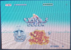
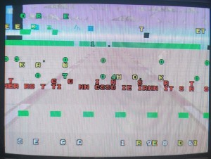
This board played fine except only put video out in the blue channel.  A couple of resistors had been clipped out near the video connector but this seemed to be a previous attempt to debug the problem rather than the cause of it.  The real problem was nearby though, the HC273 @ IC111 had failed with all the outputs stuck low.  IC111 handles green & red channels, IC104 handles blue.

20190203_115912

Next problem was lack of sound samples – speech & drums.  Synth music worked fine which pretty much guaranteed the sound CPU and program was running properly.  Samples are played by a DAC chip on the audio board, and the samples ultimately come from the ROM chips.  You can think of this process in two halves – the part of the process that sets up the address lines for the ROMs, and the part of the circuit that uses the data that comes out of the ROMs and feeds it to the DAC.  A logic probe showed all the address inputs pulsing as expected, as well as the data output at the ROMs.  The DAC inputs were mostly low, except for some random bursts of static now and again, which at least proved the amplifier was working.  I have to admit I don’t really understand what the circuit involving the DAC data does – there are a bunch of sequential adders and the top bit of the highest adder is what clocks the DAC.  It seems the adders were working but couldn’t ‘count high enough’.  Eventually I found a single dead pin, which was a corroded trace underneath one of the IC’s – what a crazy fault.  With that patched, sound was perfect.

20190211_195439

Finally inputs were tested, and the analog joystick inputs didn’t seem to function (each axis can be tested with a 5K pot).  On this board the CD4051 chip at IC125, which is used in converting the analog inputs to digital, was simply missing.  It was cleanly removed so a previous owner must have scavenged it to fix something else.  This part is easily available and a new replacement was ordered, and the game worked perfectly.

20190210_124826 20190219_184225


Pinout info from http://www.higenekodo.jp/untiku/pinout/harrier_h.htm


CPU BD (834-5797)G(AMP 50P)操作系G (AMP 50P) operation system
A7 AD VCCA7 AD VCC
A8 STICK YA8 STICK Y
A9 AD GNDA9 AD GND
A14 SHOT 3A14 SHOT 3
A15 SHOT 2A15 SHOT 2
A16 SERVICEA16 SERVICE
A17 COIN2A17 COIN2
A18 GNDA18 GND
A21 GNDA21 GND
A23 START LAMPA23 START LAMP
A24 COIN METER2A24 COIN METER 2
A25 COIN METER1A25 COIN METER1
   
B8 STICK XB8 STICK X
B14 SHOT 1B14 SHOT 1
B15 STARTB15 START
B16 TESTB16 TEST
B17 COIN1B17 COIN1
B19 GNDB19 GND
B20 GNDB20 GND
B21 GNDB21 GND
B24 +5VB24 + 5V
B25 +5VB25 + 5V
H(MOLEX 6P)モニターH (MOLEX 6P) monitor
1 RED1 RED
2 GREEN2 GREEN
3 BLUE3 BLUE
4 SYNC4 SYNC
5 GND5 GND
J(AMP 10P)電源J (AMP 10P) power supply
A1 +5VA1 + 5V
A2 +5VA2 + 5V
A4 GNDA4 GND
A5 GNDA5 GNDB1 +5VB1 + 5V
B2 +5VB2 + 5V
B4 GNDB4 GND
B5 GNDB5 GND

●CONTROL BD(834-5798)● CONTROL BD (834-5798)K(AMP 10P)電源K (AMP 10P) power supply
A1 +5VA1 + 5V
A2 +5VA2 + 5V
A4 GNDA4 GND
A5 GNDA5 GNDB1 +5VB1 + 5V
B2 +5VB2 + 5V
B4 GNDB4 GND
B5 GNDB5 GND
●ROM BD(834-5800)● ROM BD (834-5800)M(AMP 10P)電源M (AMP 10P) power supply
A1 +5VA1 + 5V
A2 +5VA2 + 5V
A4 GNDA4 GND
A5 GNDA5 GNDB1 +5VB1 + 5V
B2 +5VB2 + 5V
B4 GNDB4 GND
B5 GNDB5 GND
●SOUND BD(834-5903)● SOUND BD (834-5903)K(AMP 10P)電源K (AMP 10P) power supply
A1 +5VA1 + 5V
A2 +5VA2 + 5V
A4 GNDA4 GND
A5 GNDA5 GNDB1 +5VB1 + 5V
B2 +5VB2 + 5V
B4 GNDB4 GND
B5 GNDB5 GND(MOLEX 6P)サウンド出力(MOLEX 6P) sound output
1 SP_L+1 SP_L +
2 SP_L-2 SP_L-
3 SP_R+3 SP_R +
4 SP_R-4 SP_R-


By

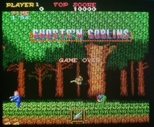
Capcom Ghosts and Goblins arcade pcb repair #2

The game played but background tiles were clearly wrong in places as were some of the sprites.  As the game has relatively few tiles I looked in the MAME tilemap viewer first of all – the background mountains started around location 0xf0 in the viewer.  It appeared the tiles from location 0xe0 and up were being drawn instead, so I wondered if bit 4 was stuck somewhere (bit 4 being 0×10 in hex which is the difference between 0xf0 and 0xe0).

20190304_080425 20190304_080348

Probing around the tilemap part of the schematics I found the A4 output line on the LS273 at 5A was indeed stuck low even while the input was pulsing.  In fact a multi-meter showed the line was physically tied to ground rather than just logically low, so some kind of internal short.  The LS273 was replaced and backgrounds were correct again.

20190304_084514

As most of the sprites were correct I suspected the eproms – there are 3 pairs and a failure of any pair would affect some sprites but not others.  Eprom 16 was indeed bad, and sprites were fixed when I burned a replacement.  Underneath the sticker the reason for the failure was obvious – some kind of physical impact had smashed the die.

20190304_195853 20190304_204408