Sega Space Harrier arcade pcb repair
A classic game, and a massive pcb set – CPU board, video board, ROM board and audio board. The game can be bench tested with just a +5V supply (no need for +12 or -5) but power has to be run separately to each board. (Forgetting to power the ROM board will give bad or missing sprites!).
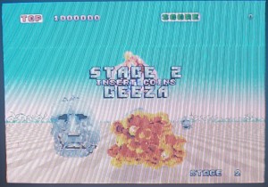
This board played fine except only put video out in the blue channel. A couple of resistors had been clipped out near the video connector but this seemed to be a previous attempt to debug the problem rather than the cause of it. The real problem was nearby though, the HC273 @ IC111 had failed with all the outputs stuck low. IC111 handles green & red channels, IC104 handles blue.
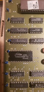
Next problem was lack of sound samples – speech & drums. Synth music worked fine which pretty much guaranteed the sound CPU and program was running properly. Samples are played by a DAC chip on the audio board, and the samples ultimately come from the ROM chips. You can think of this process in two halves – the part of the process that sets up the address lines for the ROMs, and the part of the circuit that uses the data that comes out of the ROMs and feeds it to the DAC. A logic probe showed all the address inputs pulsing as expected, as well as the data output at the ROMs. The DAC inputs were mostly low, except for some random bursts of static now and again, which at least proved the amplifier was working. I have to admit I don’t really understand what the circuit involving the DAC data does – there are a bunch of sequential adders and the top bit of the highest adder is what clocks the DAC. It seems the adders were working but couldn’t ‘count high enough’. Eventually I found a single dead pin, which was a corroded trace underneath one of the IC’s – what a crazy fault. With that patched, sound was perfect.
Finally inputs were tested, and the analog joystick inputs didn’t seem to function (each axis can be tested with a 5K pot). On this board the CD4051 chip at IC125, which is used in converting the analog inputs to digital, was simply missing. It was cleanly removed so a previous owner must have scavenged it to fix something else. This part is easily available and a new replacement was ordered, and the game worked perfectly.
Pinout info from http://www.higenekodo.jp/untiku/pinout/harrier_h.htm
| CPU BD (834-5797)G(AMP 50P)操作系G (AMP 50P) operation system A7 AD VCCA7 AD VCC A8 STICK YA8 STICK Y A9 AD GNDA9 AD GND A14 SHOT 3A14 SHOT 3 A15 SHOT 2A15 SHOT 2 A16 SERVICEA16 SERVICE A17 COIN2A17 COIN2 A18 GNDA18 GND A21 GNDA21 GND A23 START LAMPA23 START LAMP A24 COIN METER2A24 COIN METER 2 A25 COIN METER1A25 COIN METER1 B8 STICK XB8 STICK X B14 SHOT 1B14 SHOT 1 B15 STARTB15 START B16 TESTB16 TEST B17 COIN1B17 COIN1 B19 GNDB19 GND B20 GNDB20 GND B21 GNDB21 GND B24 +5VB24 + 5V B25 +5VB25 + 5V |
H(MOLEX 6P)モニターH (MOLEX 6P) monitor 1 RED1 RED 2 GREEN2 GREEN 3 BLUE3 BLUE 4 SYNC4 SYNC 5 GND5 GND |
J(AMP 10P)電源J (AMP 10P) power supply A1 +5VA1 + 5V A2 +5VA2 + 5V A4 GNDA4 GND A5 GNDA5 GNDB1 +5VB1 + 5V B2 +5VB2 + 5V B4 GNDB4 GND B5 GNDB5 GND |
|
|
||
| ●CONTROL BD(834-5798)● CONTROL BD (834-5798)K(AMP 10P)電源K (AMP 10P) power supply A1 +5VA1 + 5V A2 +5VA2 + 5V A4 GNDA4 GND A5 GNDA5 GNDB1 +5VB1 + 5V B2 +5VB2 + 5V B4 GNDB4 GND B5 GNDB5 GND |
●ROM BD(834-5800)● ROM BD (834-5800)M(AMP 10P)電源M (AMP 10P) power supply A1 +5VA1 + 5V A2 +5VA2 + 5V A4 GNDA4 GND A5 GNDA5 GNDB1 +5VB1 + 5V B2 +5VB2 + 5V B4 GNDB4 GND B5 GNDB5 GND |
●SOUND BD(834-5903)● SOUND BD (834-5903)K(AMP 10P)電源K (AMP 10P) power supply A1 +5VA1 + 5V A2 +5VA2 + 5V A4 GNDA4 GND A5 GNDA5 GNDB1 +5VB1 + 5V B2 +5VB2 + 5V B4 GNDB4 GND B5 GNDB5 GND(MOLEX 6P)サウンド出力(MOLEX 6P) sound output 1 SP_L+1 SP_L + 2 SP_L-2 SP_L- 3 SP_R+3 SP_R + 4 SP_R-4 SP_R- |












Recent Comments