Data East Gate of Doom arcade pcb repair
Board initially seemed dead, no rgb video or sync output at all. Logic probe showed that there was actually some CPU activity, but a lot of the graphics chips had no clock signal.
Attempt 1
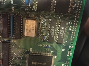
Probing some TTL around the graphics crystal revealed a LS75 chip that seemed to have a stuck output. This is a latch that outputs both Q and ‘not Q’ for input D. The logic probe shows both D and Q pulsing, but ~Q was stuck low. Replaced with another chip and it behaved exactly the same. I have to assume ~Q is intentionally grounded out somewhere on the board and isn’t used.
Attempt 2
I decided to trace out what controls the sync signal on the board. The path runs from the edge connector to the diode at FB4, then the resistor at R13, then the LS04 chip @ L11. The LS04 is used as a double invertor and the input comes from the custom graphics chip 55.
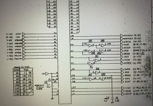
There are no schematics for Gate of Doom online, but there are for Desert Assault which is from the same era and also uses the 55 custom. This shows the same setup with sync coming from pin 157 then a double inversion, so it seems to be the same design. The schematics show the inputs to the custom – 14MHz clock to pin 11 – this was present and correct, reset on pin 15, again tested ok. Various +5V lines also tested fine. So unfortunately it seemed the custom chip was not working.
Attempt 3
All of the other inputs to the graphics custom chip 55 come from the PAL’s on the board. And they run hot – a couple quickly shooting up to 43C – so I decided to replace them all with GAL’s. I didn’t really expect much from this, as the Data East PAL’s of this era often run very hot, and I’ve never seen a failed one. Indeed this had no effect, but the GAL’s do run much cooler.
Attempt 4
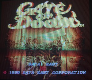
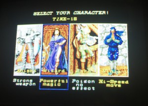
Examined the custom 55 again – applying some horizontal force to the pins revealed a handful of them moving – therefore not making good connection to the pads on the board. Really I should have noticed this before, so I reflowed the solder with a hot iron on the pins to stick them to the pads again. Success! Everything now working 100%, including sound. So even though the sync line was connected, some other control signals to the custom chip must have been disconnected.


Recent Comments