Capcom CPS1 arcade pcb repair
Well, really a non-repair in some ways, but an interesting case to look at.
This board had a glitch in the background graphics – with repeated sections and blank sections. The components involved are the custom CPS chip that generates the background, the RAM chips, the main CPU and any latches in between. The data is written to RAM from the CPU through two LS245 latches(the red path), then the graphics chip reads from RAM through another two LS245 latches (the green path).
You can rule this out being a RAM fault – because the RAM is paired, so it would need two different chips to fail in the exact same way which is unlikely (if only 1 chip failed then you would have bad tiles/colors not good tiles in the wrong place).
You can rule this out being a CPU fault because of the repeated data – the CPU can’t write one thing and have it go to different places at once in the RAM. The RAM only accepts one address at once.
For the same reason the LS245 latches in between the CPU and RAM must be ok, they couldn’t cause a ‘repeat’.
So this must be a fault in how the graphics chip is reading the RAM (an addressing problem). Initially I hoped for an easy fix as a broken trace on the board would cause this exact problem (with an address line broken the same data would be read at multiple addresses). However the traces all run on the top of the board where a scratch is unlikely, and everything was perfect. A multimeter confirmed continuity all the way from the graphics chip to the latches to the RAM (it also confirmed it to the top B board but I knew that wasn’t at fault as I had already tried out a known working B board).
I ‘mocked up’ the problem in the MAME debugger. By forcing RAM line 0×400 (or something) to always be low I repro’d the problem (this means that data at say 0×600 reads the same as data as 0×200 (the ’4′ is masked low), 0×602 same as 0×200, etc. So 1 bit was stuck low in either the LS245 latch, or the CPS-A-01 graphics chip itself. Removing surface mount chips via hot air is quite easy – replacing them is much harder… but eventually both were replaced with others from a parts board – and the exact same fault remained ![]() That means the fault was definitely within the unreplaceable CPS-A chip (well, you could replace it with another from a working board, but much easier just to use that board).
That means the fault was definitely within the unreplaceable CPS-A chip (well, you could replace it with another from a working board, but much easier just to use that board).
And in this case, that’s what I did – an A board from a Magic Sword with no sound and bad B board was swapped in to keep the SF2 World Warrior working.
No Sound fix
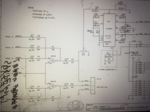
A logic probe showed the audio Z80 CPU was running, so I examined the analog audio output by attaching a pair of power speakers at various points on the board. At first the op-amp at IC138 (pins 1, 2 and 3), then the volume control (VR1), then inputs to the power amp @ 16A. Faint sound was heard at all points so the power amp was likely the problem. The amp was removed from the board with the dead CPS-A and soldered in to give a fully working SF2 World Warrior.


Recent Comments